
Development of A Gear Box of the Truck
Naberezhnochelninsky Institute (branch) Kazan Federal University, Russian Federation, 423812, Naberezhnye Chelny, pr.Syuyumbike, 10A,
Corresponding Author E- Mail: iis_kfu@mail.ru
DOI : http://dx.doi.org/10.13005/bbra/2107
Download this article as:
![]()
The kinematic scheme hydromechanical differential high-torque CVT. Developed the design of the continuously variable transmission of the truck with a high-torque differential hydromechanical CVT.
KEYWORDS:hydra-mechanical gear train; continuously variable transmission; differential hydra-mechanical variator, mechanical diagram; high-torque differential hydra-mechanical variator
Introduction
Continuous variable transmission enables to combine effectively the engine performance with different modes of the vehicle operation. However, the existing mechanical continuous variable transmissions have a significant disadvantage – the maximum transmittable torque of 300 ÷ 350 Н∙м, which prevents their use in trucks transmissions. The continuous variable transmissions are still not widely used in trucks transmissions also due to their existing significant shortcomings as compared to mechanical speed transmission gearbox (size, weight, efficiency, production costs, etc.).
High torque differential hydro-mechanical variator used in the construction of the continuous variable transmission allows to meet the following tasks:
– Increase the maximum value of the transmitted torque;
– Increase the mechanism efficiency and reduce the dimensions due to the possibility to operate at high pressure values
– Provide automatic torque control on the output shaft, without control systems, depending on the changes in the external load and the control range of trucks [1].
High torque differential hydro-mechanical variator (HTHMV)
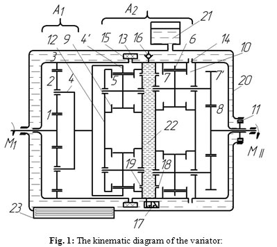
High torque differential hydro-mechanical variator is designed for the continuous automatic converting of rotary motion between the motor shaft and the shaft of the working body of the machinery in order to ensure the optimal mode of the joint operation of the engine and the variator at an arbitrarily changing value of the external load on the working body. Kinematic HTHMV diagram shown in Figure1 is applicable to the trucks transmission; it has a large transformation ratio and can operate at high fluid pressure values of above 20 MPa.
The housing 12 of the differential high-torque hydro-mechanical variator rests on the bearings installed in the oil-filled crankcase 20. The crankcase has an expansion tank 21 to compensate for thermal expansion of the oil. The first differential stage of the variator is a mechanical differential mechanism consisting of the input shaft 1, satellites 2, the output unit 3 and the carrier 4. The second differential stage is a hydro-mechanical differential transducer having two planetary gear sets, one of which is formed by kinematic units of the multiple gear hydro-pump 9 consisting of a crown wheel 4’ coupled by the internal engagement with satellites 5, and the second – by kinematic units of the multiple gear hydro-motor 10 with two crown satellites 7-7’, the internal engagement gears thereof 7 are connected with the crown wheel 6, and those of the outer engagement 7’ – with the central sun gear 8. The hydraulic pump and the motor have input 15 and 18, output 14 and 19 ports, their number being equal to the number of satellites at the hydraulic pump and the motor [2, 3].
The hydraulic annular channel 22 is equipped with an automatic bypass valve 16 and the controlled valve 17. Between the carrier 12 and the crankcase 20 there is a free-wheel clutch 11, on the input ports of the pump there is a filter 13, and there is a heat exchanger 23 mounted at the bottom of the crankcase 20.
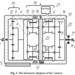 |
Figure 1: The kinematic diagram of the variator:
|
At a fixed carrier 12, the torque М1 from an external power source is transmitted to the input unit 1of the differential mechanism А1, which rotates at a speed of n1 and is transmitted through satellites2 to the carrier of the differential 4 of the kinematic unit 4-4′. Herewith, the unit 4-4′ rotates in the same direction as the input unit 1. Rotation of the unit 4-4′ and satellites 5 creates a flow of the working fluid determined by the parameters of the equation
![]()
where M 4-4 M TH– the torque on the input shaft of the hydraulic pump, N∙m;
рн – fluid pressure, МPа;
VГН – the working volume of the hydraulic pump, m3.
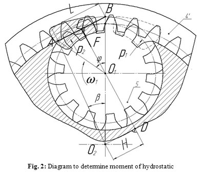
A hydrostatic moment on the carrier is a distinctive feature of the hydraulic machines with internal engagement gears. Figure 2 presents the diagram for determining of the hydrostatic moment. Projections of curved surfaces of gear crowns, which are pressed by the liquid stream, are reduced to a rectangular area of the length L and the width b. The resultant of the pressure forces of the liquid F is directed perpendicular to the direct line AB and creates an unbalanced hydrostatic torque on the carrier.
![]()
where Н – the shoulder of the force F, m.
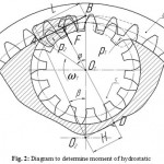 |
Figure 2: Diagram to determine moment of hydrostatic |
At the same time, the moment resultant of the pressure forces on the crown wheel is equal to zero, because the resultant vector of the pressure forces comes through the crown wheel rotation axis [4, 5].
In general case, the magnitude of the force F is equal to
![]()
where pн – fluid pressure, МPа; L – the length of the chord passing through the points А and В, m; b – the width of the tooth, m.
The final value of the hydrostatic moment on the carrier is equal to
![]()
where i54’ – gear ratio hydraulic pump.
At the driving crown gear .Mrc =MTH
The carrier 12 receives the reactive moment from the mechanical differential mechanism А1 equal to ,
M12Al = Mli13, directed opposite of the input unit 1 rotation
When using a gear pump with internal engagement gears with two or more driven wheels, a moment let to the gear 4′ (the pump moment) is received by the resistance moments acting at the hydraulic pump gears 4′ and 5. In this case, the resistance moment on the unit 5 defines the value of the reaction moment on a carrier 12 which is equal
![]()
The carrier 12 is influenced by an unbalanced hydrostatic moment resulting from the pressure of the working fluid flow equal
![]()
The value of the resistance moment at the unit 5 is determined from the equation
.![]() and moments’ redistribution ratio in the hydraulic pump
and moments’ redistribution ratio in the hydraulic pump
That is .
The moments , and sum is equal to
![]()
and has the same direction as the one of the input unit 1 rotation. This moment is the reference point, it determines the maximum transformation rate basing on the equilibrium conditions of the carrier 12, under the action of the total reactive moment from the hydraulic motor [3, 6].
The working fluid flow through the output ports of the hydraulic pump 19 enters the annular channel 22 and through the input ports of the hydraulic motor 18 in its working cavity formed by the troughs of the gear wheels 6 and 7. The torque on the output shaft of the motor is equal to
![]()
where рН – fluid pressure, МPа;
VГМ – the working volume of the hydraulic motor, m3;
![]()
– hydraulic gear ratio;
– the torque at the output shaft of the motor, N·m;
– the torque at the output shaft of the variator, N·m;
– the gear ratio of the gearing between the gears 7’ и 8.
The reactive moments occur on the carrier at presence of the resistance on the output shaft of the hydraulic motor in the direction opposite to the rotation of the input shaft. When a working fluid is fed in the working spaces of a gear hydraulic motor with internal engagement gears and with two or more satellites the same as in hydraulic pumps, there occur moments of the resistance on the gears 6 and 7. In this case, the moment of resistance on the unit 6 determines the value of the reactive moment from the hydro-motor on the carrier 12,
which is equal .![]() At further transmission of torque from the crown gear 7’ to the central sun gear 8, there occurs an reaction moment equal to .
At further transmission of torque from the crown gear 7’ to the central sun gear 8, there occurs an reaction moment equal to .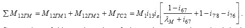
Similarly to the hydraulic pump, the unbalanced hydrostatic moment also resulting from pressure of the working fluid flow directed towards the input shaft, operates in the a hydraulic motor with internal gear and equal . As a result of this moment the total reaction moment from the motor on the carrier 12 is reduced by this value and is equal

Gear ratios of kinematic units of the variator are determined basing on the equilibrium conditions of the carrier 12 at a predetermined transformation ratio

The carrier 12, which is common for the two differential stages, and at presence of resistance moment on the output shaft 8 Mc =- M11 is in a state of equilibrium and the number of its revolutions is n12 = 0, and the number of the output shaft revolutions of the variator is n11 =n1/K (K – transformation coefficient). At| Mc|>|−M11 a difference of moments on the carrier 12 is received by a freewheel 11. At reducing the number of revolutions of the output shaft till n11 =0 under the load exceeding a targeted one, the pressure in the annular cavity increases to the pressure of the relief valve 16 automatic triggering; and the difference between the liquid flow through the pump and motor flows from the ring channel 22 into the internal housing cavity 20. Due to the significant rise in temperature of the working fluid at its overflow through the slits of the valve 16, such operation mode may be allowed only for a short while at the starting from standstill of the vehicle.
When reducing the load on the output shaft II, the reaction moment on the carrier 12 by the motor decreases, the flow of hydraulic power reduces, while the mechanical total moment ΣМ12 formed by the work of differential stages А1 and А2 with a constant number of revolutions of the input shaft I is transmitting capacity by the parallel flow of mechanical power. The difference between the sum of moments and the reaction torque leads to the rotation of the carrier 12 in the same direction as the input I and output II shafts, and the number of revolutions of the output shaft II increases from to which determines the range of automatic adjustment of the variator ivar = ÷1. Herewith occurs a redistribution of power flows by the hydraulic and mechanical circuit and at all the power is transmitted by the mechanical circuit [6, 7, 8].
The design of the continuous variable transmission of the tow tractor
The truck-tractor KAMAZ-5460 was adopted as a prototype for calculation of the main parameters of the high-torque hydro-mechanical variator, its diagram is shown in Figure 1. Initial data for calculation:
– The gear ratio of the GB first stage – 13.86;
– The gear ratio of the GB highest stage – 0.84;
– Maximum engine torque – 1470 Н∙м;
– Rated motor power – 265 kW
– Axle ratio – 5.11;
– Static wheel radius – 0.478 m.
Preliminary calculations showed that it is necessary to significantly increase the size of the variator housing to maximize the coefficient of transformation; therefore it is appropriate to use two-step splitter in addition to the variator, which also would provide an overdrive transmission and reversing.
Calculation of gear ratios of the splitter should be carried out in the following sequence:
- The required maximum transmission gear ratio is determined for overcoming the maximum road resistance
![]()
where ψmax – the maximum coefficient of road resistance; Ga – the full weight of road train, N; rк – kinematic wheel radius, m; Memax – the maximum torque of the engine, N∙m; ηтр – transmission efficiency.
- The minimum transmission gear ratio is determined for automobile train propulsion with a maximum speed:
![]()
where nV – the rotational speed of a crankshaft of the engine when driving with a maximum speed of; Vmax – the maximum speed of motion of lorry convoy.
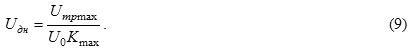
- The gear ratio of an overdrive splitter transmission Uдв is set up, and the axle ratio is defined by the Uтрmin value:
- Maximum transformation ratio of the variator Kmax is set basing on the maximum allowable dimensions of the gearbox housing and the gear ratio of the splitter lower stage is defined:
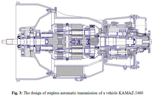 |
Figure 3: The design of stepless automatic transmission of a vehicle KAMAZ-5460 |
Upon setting the maximum variator transformation ratio, it is necessary to define the basic parameters of the kinematic units of the variator. The calculation showed that it is possible to size the high-torque hydro-mechanical variator with the following parameters into the given dimensions of the existing GB:
– The gear ratio of the differential mechanism at the input of the variator i13 = -3,0;
– The gear ratio of the differential pump i4’5 = 0,31;
– The gear ratio of the differential hydro-motor i67 = 3,55;
– The gear ratio of the gearing at the output of the hydro-mechanical variator i7’8 = -2,29;
– Hydraulic gear ratio iг = 0,766;
– Pump module mн = 6,0 мм;
– Motor unit mм = 6,0 мм;
– Width of the hydraulic pump teeth bн = 43 мм;
– Width of the hydraulic pump teeth bм = 92 мм;
– The gear ratio of the low split gear Uдн = 1,95;
– The gear ratio of the high split gear Uдв = 0,84;
– Axle ratio U0 = 5,11.
The design of the continuous variable transmission with high-torque hydro-mechanical variator of the truck-tractor KAMAZ-5460 is presented in Figure 3.
Conclusion
The comparative analysis of the automatic transmissions designs composition, wedge catching and toroidal variators produced by modern automotive industry in different countries, shows a high degree of design and technological continuity in respect of the existing production of gears and hydraulic machines, a high degree of unification, a significantly less cost of materials and labor and, accordingly- much lower cost.
High-torque differential hydro-mechanical variators in the automotive industry used as automatic transmissions in trucks, allow the engine in co-operation with them to work in the regime of equal capacity, at the external load changing over the entire range, which leads to an optimal degree of capacity utilization and, accordingly, the significant reduction in fuel consumption. Reached technical results provide the multifunctional use of the proposed invention in all fields of engineering.
References
- Sharipov V.M. Building and calculation of tractors / Moscow: Publishing Mechanical Engineering, (2004). – 590 p.
- Mavleev, I.R. Development of efficient schemes and designs high-torque hydromechanical CVTs for vehicles: Author. dis. Cand. tehn. Sciences. – Naberezhnye Chelny, (2007). – 19 p. [Мавлеев И.Р. Разработка рациональных схем и конструкций высокомоментных гидромеханических вариаторов для транспортных средств: Автореф. дис. Канд. техн. Наук. – Набережные Челны, (2007). – 19 с.]
- Salakhov, I.I. The development of automatic transmissions rational schemes, based on the planetary system of universal multi-threaded differential mechanism: Author. dis. Cand. tehn. Sciences. – Izhevsk: M.T.Kalashnikov IzhSTU, (2013). – 23 p. [Салахов И.И. Разработка рациональных схем автоматических коробок передач на основе планетарной системы универсального многопоточного дифференциального механизма: Автореф. дис. Канд. техн. Наук. – Ижевск: ИжГТУ М. Т. Калашников (2013). – 23 с.]
- Patent №2347966 RF IPC F16H 47/04. Differential hydro-mechanical high-torque CVT / Voloshko V.V., & Mavleev I.R. Publ. 27.02.2009, Bull. № 6. [Патент №2347966 РФ, МПК F16H 47/04. Высокомоментный дифференциальный гидромеханический вариатор / Волошко В.В., & Мавлеев И.Р. Опубл. 27.02.2009, бюл. №6.]
- Patent №2384773 RF IPC F16H 3/44. Automatic speed planetary gearbox / Voloshko V.V., & Salahov I.I. Publ. 20.03.2010, Bull. № 8. [Патент №2384773 РФ, МПК F16H 3/44. Автоматическая ступенчатая планетарная коробка передач/ Волошко В.В., & Салахов И.И. Опубл. 20.03.2010, бюл. №8.]
- Ildar Ilgizarovich Salakhov*, Vladimir Vladimirovich Voloshko, Ilnur Dinaesovich Galimyanov and Ildus Rifovich Mavleev Universal Differential Mechanism / Biosciences Biotechnology Research Asia, Vol. 11(3), 2014, 1553-1557 pp., https://www.biotech-asia.org/currentissue.php?pg=2
- Ildar Ilgizarovich Salakhov*, Ildus Rifovich Mavleev, Ildar Rafisovich Shamsutdinov, Ruslan Ramilevich Basyrov and Voloshko Vladimir Vladimirovich Research and Development of Hydro-Mechanical Differential Variator / Biosciences Biotechnology Research Asia, September 2015., Vol. 12(1), 619-625 pp., http://dx.doi.org/10.13005/bbra/1705
- Ildar Ilgizarovich Salakhov*, Ildus Rifovich Mavleev, Eduard Nikolaevich Tsybunov, Ruslan Ramilevich Basyrov and Niyaz Ilgizarovich Salakhov Car Gearbox on the Basis of the Differential Mechanism / Biosciences Biotechnology Research Asia, September 2015., Vol. 12(Spl. Edn. 2), 41-44 pp., https://www.biotech-asia.org/specialedition.php?issue=SE%20SEP%2015
Accepted on: 13 April 2016


![]()
![]()
