
Determination of the Efficiency of the Hydro-Mechanical Differential Variator
Naberezhnochelninsky Institute (branch) Kazan Federal University, Russian Federation, 423812, Naberezhnye Chelny, pr.Syuyumbike, 10A,
Corresponding Authors E-mail: iis_kfu@mail.ru
DOI : http://dx.doi.org/10.13005/bbra/2101
Download this article as:
![]()
The author has carried out the analysis of dynamic-coupled automatic transmissions and regarded the prospects of their application and development. New design of continuously variable transmission based on differential hydra-mechanical gear train was developed and covered by RF patents No2298125 and No2347966. Principles of work performance for high-torque differential hydra-mechanical gear train based on interoperation equableness of moments opposing one another that are produced at the gear carrier owing to inner forces of differential stages as well as self-actuated pressure variation and hydraulic fluid consumption change when it comes through hydraulic pump and hydraulic actuator.
KEYWORDS:hydra-mechanical gear train; continuously variable transmission; differential hydra-mechanical variator; mechanical diagram; high-torque differential hydra-mechanical variator
Introduction
Mechanical losses are mainly those due to friction between the parts of the machine working body. These losses depend on the difference in fluid pressure acting on the parts of the working body and the rotation speed of these parts. The largest part of the total number of losses is accounted for the mechanical losses. So particular attention should be paid to their reduction [1, 2].
Differential hydro-mechanical variator and principle of operation
Differential hydro-mechanical variator is a combination of two mechanisms, namely- the reduction gearing unit and the gear hydraulic machine. The ratios changes of the mechanical and hydraulic power flow occur by the variator operation as part of the vehicle transmission. The variator will have the lowest efficiency factor at setting off, as in this case it will operate as a hydrostatic transmission, in which there occur volumetric, hydraulic and mechanical losses. With the rotation speed of the variator (carrier) housing increase there happens the redistribution of power flow, and the loss ratio in the hydraulic power flow is reduced resulting in the increased overall efficiency of the variator, up to a value close to 100% at the variator rotation in self-latching mode (the machine operates as a shaft). Two parallel power flows shall be considered by determination of the overall variator efficiency.
Energy losses in the hydraulic power flow consist of the mechanical, hydraulic and volumetric losses. Almost all these losses are converted into heat causing the heating of the machine parts and the working fluid passing through its internal cavities [3, 4].
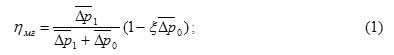
The mechanical efficiency value of the hydraulic machine can be expressed in terms of dimensionless variables:
![]()
where , – ![]() the dimensionless pressure drops; – coefficient of resistance.
the dimensionless pressure drops; – coefficient of resistance.
Hydraulic losses are made up of energy losses in the input and output cavities of the machine, at the entrance and exit of the variable working body. Hydraulic losses are mainly local and losses and occur at any change in the shape or direction of the flow. The values of the hydraulic efficiency can be expressed in terms of dimensionless variables:
![]()
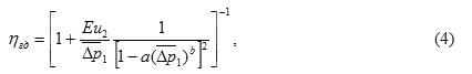
where Eu2 – the criterion for Euler; а и b – typical coefficients of hydraulic.
Volume losses can be divided into losses due to leakages of liquid from the cavities with higher pressure into the cavities with low pressure, and losses due to incomplete filling of the working chambers of the machine with fluid during the first phase of the working cycle. The value of volumetric efficiency can be expressed in terms of dimensionless variables:
![]()
![]()
where and![]() the dimensionless pressure drops at the hydraulic pump and the hydraulic motor.
the dimensionless pressure drops at the hydraulic pump and the hydraulic motor.
Overall efficiency of hydraulic machines:
![]()
![]()
The parameters needed to determine the efficiency of hydraulic machines in the pump motor and hydraulic motor mode are summarized in Table 1.
Table 1. The parameters for the calculation of gear efficiency hydraulic
| Parameter | The value of the parameter |
| а | 0,03-0,1 |
| b | 3-4 |
| h | 0,02-0,04 |
| k | 3∙10-3-1,2∙10-2 |
| Ω | 0,04-0,2 |
| Λ | |
| 0,5∙10-2-1,5∙10-2 | |
| 6∙104-20∙104 | |
| ()г | |
| ()д | |
Energy losses in the mechanical power flow can be considered as loss in the planetary gear mechanisms. In practice the planetary or differential transmissions are usually reduced by inverting to a simple transmission with fixed axes, assuming that the additional rotation, imparted to the entire mechanism in general, does not change anything in the moment as a result of transformation, and consequently, in the forces of friction operation [4]. It is necessary to distinguish between two cases: 1) the driving parts are the carrier and one of the central wheels; 2) both central wheels are driving, and the carrier is a slave one.
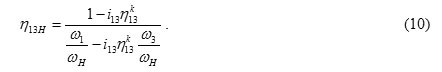
In the first case, differential transmission efficiency shall be defined by the formula:
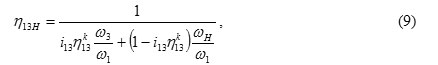
where i13 – the gear ratio of the differential mechanism; – transmission efficiency with fixed axles; k – equal to ±1 depending on whether the element 1 facing the transfer slave master; ω1 – the angular velocity of rotation of the Central wheel 1; ωН – angular velocity of rotation of the carrier H; ω3 – the angular velocity of rotation of the Central wheel 3.
In the second case the resistance forces moment is applied to the carrier H and the efficiency is determined by the formula:
The reliable and, perhaps, the only correct way to determine the variator efficiency is to split it into separate elements, calculate their efficiency, and basing on this data to define the total efficiency of the variator [5, 6, 7].
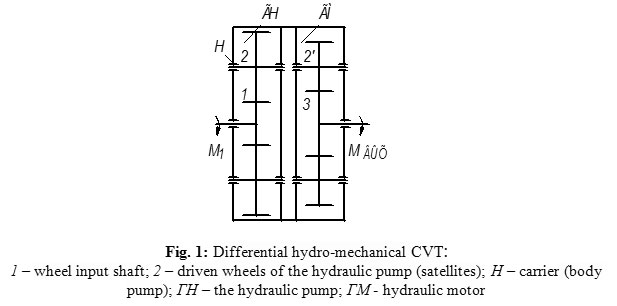 |
Figure 1: Differential hydro-mechanical CVT:1 – wheel input shaft; 2 – driven wheels of the hydraulic pump (satellites); Н – carrier (body pump); ГН – the hydraulic pump; ГМ – hydraulic motor |
The variator shown in the Figure 1 should be viewed as a series connection of two hydro-mechanical differential mechanisms. Herewith, the first hydro-mechanical differential mechanism, being at the same time a hydraulic pump, manifests power separation into two parallel streams. That means, it is necessary to consider the differential parallel connection of two mechanisms in order to determine the efficiency of the differential hydraulic pump: a hydraulic pump and a mechanical differential, which are the consumers of one and the same source of motive power. [5].
Thus, the total power on the driving unit of the hydro-mechanical differential mechanism
where NH1 – the power consumed in mechanical stream, kW; NГН – the power consumed by the hydraulic flow, kW; ηН1 – The efficiency of a mechanical flow; ηГН – Efficient hydraulic flow.
Proceeding from the common definition of the machine efficiency
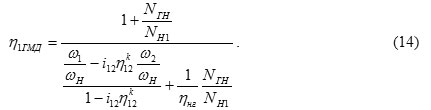
where η1ГМД – the overall efficiency of the differential pump.
By dividing the numerator and denominator by NH1 the formula (12) is reduced to the
Using formulas (7) and (10) the efficiency of the differential pump shall be to determined as
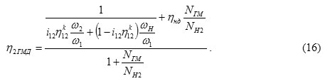
Two parallel power flows are summed up on the differential hydraulic motor. It means that for determining the efficiency of differential hydraulic motor we should consider the parallel connection of two mechanisms, the hydraulic motor and the mechanical differential, which are the sources of motive power for energy supply of one user [6, 7].
Overall efficiency in this case
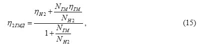
where η2ГМД – total efficiency of the differential hydraulic motor; NH2 – the power supplied for mechanical stream, kW; NГМ – the power supplied by the hydraulic flow, kW; ηН2 – efficiency mechanical stream; ηГМ – efficient hydraulic flow.
Using formulas (8) and (9) it is possible to define the efficiency of differential hydro-motor
The efficiency of the variator shown in Figure 1 is expressed by the equation
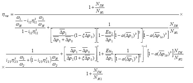
The greatest influence on the variator efficiency is rendered by fluid pressure and gear ratios of the differential stage. These dependences are shown in Figures 2 and 3.
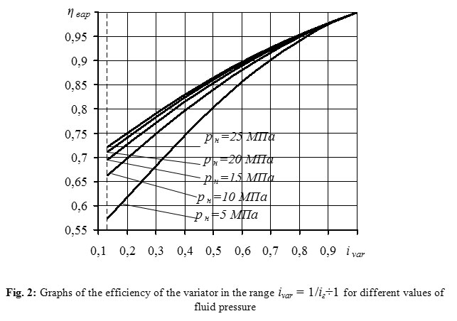 |
Figure 2: Graphs of the efficiency of the variator in the range ivar = 1/iг÷1 for different values of fluid pressure |
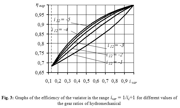 |
Figure 3: Graphs of the efficiency of the variator in the range ivar = 1/iг÷1 for different values of the gear ratios of hydromechanical |
Conclusion
Comparing to a prototype, infinitely variable adjustment of kinematic and power parameters is implemented at a total absence of any steering system thus reaching the simplicity of design.
The comparative economic analysis of product profiling of self-actuated gear boxes, beveled chain variators and toroid progressive transmissions produced by the modern automobile industry of different countries shows the high degree of design-engineering consistency of operations in relation to the existing level of geared transmissions and hydraulic machines manufacture, high extent of universalization, considerably less cost of materials and labor effort and, accordingly, lower cost of production.
In automobile industry high-torque differential hydra-mechanical gear trains used in the quality of automatic transmissions for automotive trucks makes the possible to work in the mode of equal powers when the external load varies within the whole range, what brings to optimal power use and, correspondingly, to the considerable diminishment of fuel consumption.
The attainable technical results provide for multifunctional use of the given invention in all fields of machine building.
References
- Mavleev, R. Development of efficient schemes and designs high-torque hydromechanical CVTs for vehicles: Author. dis. Cand. tehn. Sciences. – Naberezhnye Chelny, (2007). – 19 p. [Мавлеев И.Р. Разработка рациональных схем и конструкций высокомоментных гидромеханических вариаторов для транспортных средств: Автореф. дис. Канд. техн. Наук. – Набережные Челны, (2007). – 19 с.
- Salakhov, I.I. The development of automatic transmissions rational schemes, based on the planetary system of universal multi-threaded differential mechanism: Author. dis. Cand. tehn. Sciences. – Izhevsk: M.T.Kalashnikov IzhSTU, (2013). – 23 p. [Салахов И.И. Разработка рациональных схем автоматических коробок передач на основе планетарной системы универсального многопоточного дифференциального механизма: Автореф. дис. Канд. техн. Наук. – Ижевск: ИжГТУ М. Т. Калашников (2013). – 23 с.
- Patent №2347966 RF IPC F16H 47/04. Differential hydro-mechanical high-torque CVT / Voloshko V.V., & Mavleev I.R. Publ. 27.02.2009, Bull. № 6. [Патент №2347966 РФ, МПК F16H 47/04. Высокомоментный дифференциальный гидромеханический вариатор / Волошко В.В., & Мавлеев И.Р. Опубл. 27.02.2009, бюл. №6.]
- Patent №2384773 RF IPC F16H 3/44. Automatic speed planetary gearbox / Voloshko V.V., & Salahov I.I. Publ. 20.03.2010, Bull. № 8. [Патент №2384773 РФ, МПК F16H 3/44. Автоматическая ступенчатая планетарная коробка передач/ Волошко В.В., & Салахов И.И. Опубл. 03.2010, бюл. №8.
- Ildar Ilgizarovich Salakhov*, Vladimir Vladimirovich Voloshko, Ilnur Dinaesovich Galimyanov and Ildus Rifovich Mavleev Universal Differential Mechanism / Biosciences Biotechnology Research Asia, Vol. 11(3), 2014, 1553-1557 pp., https://www.biotech-asia.org/currentissue.php?pg=
- Ildar Ilgizarovich Salakhov*, Ildus Rifovich Mavleev, Ildar Rafisovich Shamsutdinov, Ruslan Ramilevich Basyrov and Voloshko Vladimir Vladimirovich Research and Development of Hydro-Mechanical Differential Variator / Biosciences Biotechnology Research Asia, September 2015., Vol. 12(1), 619-625 pp., http://dx.doi.org/10.13005/bbra/1705
- Ildar Ilgizarovich Salakhov*, Ildus Rifovich Mavleev, Eduard Nikolaevich Tsybunov, Ruslan Ramilevich Basyrov and Niyaz Ilgizarovich Salakhov Car Gearbox on the Basis of the Differential Mechanism / Biosciences Biotechnology Research Asia, September 2015., Vol. 12(Spl. Edn. 2), 41-44 pp., https://www.biotech-asia.org/specialedition.php?issue=SE%20SEP%2015
Accepted on: 09 April 2016


![]()
![]()
