

Manuscript accepted on :
Published online on: 14-12-2015
Onboard Flight Safety Support System Development for Low-Altitude Flights of Light Aircraft
I. Akhrameev Vasily1, V. Akhrameev Ivan2, V. Babichenko Andrey3, S. Zemlyaniy Egor4 and S. M. Sokolov5
1Cand. of Techn. Sciences, Associate Professor, ZAO «Techaviacomplex», Gromov Flight Research Institute, Zhukovsky, Moscow Region, 140182 Russian Federation, 2ZAO «Techaviacomplex», Gromov Flight Research Institute, Zhukovsky, Moscow Region, 140182 Russian Federation, 3Doctor of Techn. Sciences, Professor, OAO “Ramenskoye priborostroitelnoye konstruktorskoye biuro”(Ramenskoye Design Company JSC), 2 Gurieva, Ramenskoye, Moscow Region, 140103 Russian Federation, 4Postgraduate Student, Bauman Moscow State Technical University, 2-aia Baumanskaya str. 5, Moscow, 105005 Russian Federation, 5Doctor of Phys.-Math. Sciences, professor, Keldysh Institute of Applied Mathematics RAS, 4 Miusskaya Sq., Moscow, 125047 Russian Federation.
DOI : http://dx.doi.org/10.13005/bbra/1959

ABSTRACT: The examined scientific and technical problem concerns providing flight safety for Small Aviation and General aviation (GA) aircraft with the use of onboard software and hardware. Proposed by the authors approach to the selection of scientific and engineering principles and methods, implemented in the algorithms of onboard computers when assessing the risk of a situation is based on the classification of the main causes and the corresponding types of aviation accidents and incidents during low-altitude flights of light aircraft in airspace with a high intensity of air traffic by the main typical features revealed on the basis of flight accidents analysis. The authors did an in-depth study on a rational option of complex vision system configuration, determined and justified a set of basic parameters of all the other components of the onboard system experimental sample, analyzed and compared options of possible technical solutions, on the basis of which selection and justification of the optimal variant of technical configuration by the hardware composition and the software structure of for the prototype.
KEYWORDS: flight safety; light aircraft; small aviation; general aviation; onboard software and hardware; piloting errors; navigation errors; aircraft collision in the air; collision with ground obstacles; low-altitude flight; crew information support and intellectual support; technical vision system
Download this article as:| Copy the following to cite this article: Vasily I. A, Ivan V. A, Andrey V. B, Egor S. Z, Sokolov S. M. Onboard Flight Safety Support System Development for Low-Altitude Flights of Light Aircraft. Biosci Biotechnol Res Asia 2015;12(3) |
| Copy the following to cite this URL: Vasily I. A, Ivan V. A, Andrey V. B, Egor S. Z, Sokolov S. M. Onboard Flight Safety Support System Development for Low-Altitude Flights of Light Aircraft. Biosci Biotechnol Res Asia 2015;12(3). Available from: https://www.biotech-asia.org/?p=2169 |
Introduction
The Russian segment of the small aircraft market is only emerging, however the potential demand for light flying vehicles (FV) due to large spaces, weak road network, increasing purchasing power of the population and the desire of its active part for mobility is very high. In addition, aviation of local airlines begins to grow rapidly. As a rule, flight experience of pilots flying small aircraft of local airlines is not significant. Experience of amateur pilots, flying aircraft of the general aviation (GA), is even less. That is why according to the world statistics a larger share of accidents occurs with light aircraft (aircraft of local airlines) and GA aircraft in comparison with heavy (medium-range and long-range) aircraft operated by pilots-professionals with extensive experience.
As the statistics analysis demonstrates (Akhrameev, Goman, Merkulov, & Klumov, 1989; Akhrameev, & Goman, 1989; Ahrameev, & Goman, 1991; Akhrameev, 1998; Report of the Interstate Aviation Committee (IAC), 2008), the majority of air accidents occur either due to various equipment failures (15 … 20%) or due to piloting errors made in the process of piloting (about 80%). The article (Babichenko, & Zemlyaniy, 2014) examined some of the factors that lead to piloting errors associated with both psycho-physiological qualities of pilots and the nature of the problems to be solved. It is shown that with the objectively growing complexity of aircraft control tasks, crews intellectual support is necessary for flight safety, i.e. giving the functions of an intelligent system to the onboard equipment; it supposes creation of onboard knowledge base, inference engine and the corresponding interface. Implementation of this provision in the full form means building an onboard expert flight safety system (Babichenko, and Zemlianiy, 2014, Shishkin, 2005). Unfortunately, nowadays there are no similar solutions for GA aircraft, due to reasons of high cost and development complexity. At the same time, solutions simplifying the implementation of intellectual support with traditional algorithmic and schematic methods are partially embedded in military FV production. Therefore, taking into account the relevance of diagnostics of critical flight modes for GA aircraft, including those associated with the danger of aircraft collision in the air and collisions with ground obstacles; at this stage it is appropriate to use existing solutions for intellectual support for their adaptation and further development. Diagnostic algorithms integration of with algorithms for control automation in the manual (giving recommendations to pilots) or in the automatic mode will significantly improve flight safety for Small Aviation and GA aircraft.
Below we describe the formation principles of flight and navigation information on current and limiting conditions of space maneuvering, warning signals and steering marks delivering for rational collision avoidance with the ground and air targets, recovery from the maximum allowable flight speeds, stall and spin recovery, other abnormal situations that will allow creating of onboard flight safety support system for GA aircraft. Applied research described in this article is carried out with financial support of the state represented by the Ministry of Education and Science of the Russian Federation under the Agreement #14.579.21.0051 from September 16, 2014. A unique identifier of applied research is RFMEFI57914X0051.
Formulation of the problem
The new system is based not only on the reliability of the principal functions as intended but also on small sizes, low power consumption and a low price, which should ensure its massive use, including by amateur pilots in GA aircraft. The new system must provide “high-layered” protection of inexperienced pilots from errors in piloting and navigation and should be easily adapted to any class of light FV and unmanned FV.
To improve flight safety and relieve the crew from increased stress, the onboard system algorithms should ensure collision avoidance in the air and collision avoidance with ground obstacles when flying at low altitudes, and in order to improve the accuracy of information on other FV and obstacles, it is possible to use a small-sized radar complex that includes all such auto vision system sensors as a video camera, thermal imager, laser radar and radio-locating station of a millimeter range or in combinations
Detection and parry of piloting
and navigation errors
It is difficult to develop an automatic system designed for the detection of a very large number of possible types of hazards. However, with the use of statistical flight accidents analysis (Ahrameev, Goman, Merkulov, & Klum, 1989; Ahrameev, & Goman, 1989; Ahrameev, & Goman, 1991; Akhrameev, 1998; report of the Interstate Aviation Committee (IAC), 2008), it is possible to allocate a set of commonly encountered typical situations that are characterized by certain common features, by which the situations can be identified.
Crew Errors during the flight at low altitudes can be divided into piloting (during maneuvering and at a flight level, descending, during approach, circling approach, at all stages of landing, during take-off, departure, climb, and when changing a flight level etc.) and navigation (the flight plan or flight profile violation , transition altitude or transition level missing , waypoints passing , loss of orientation, dangerous or restricted areas entering inadequate fuel rest estimating, etc.).
Existing onboard flight safety tools work in the alert mode and do not provide an effective forecast for further development of arising special situations , thereby depriving the pilot of the most important resource – the lead time for making and implementing decisions. Therefore, to ensure safety it is necessary to provide:
- analysis of aircraft dynamics and a state of its onboard systems;
- diagnostics of occurrence of dangerous and critical flight modes;
- prediction of a trajectory and other flight parameters;
- warning;
- selection of the optimal solution to prevent further development of a difficult situation and recommendations for an output to recover from it.
To enhance the security of maneuvering at low altitudes, the onboard flight safety system (OFSS) must prevent:
- getting into a complex aircraft attitude at low altitudes;
- collision with the ground as a result of incorrect implementation of vertical maneuvers, loss of spatial orientation, when flying over difficult terrain (especially hilly or mountainous) in conditions of poor visibility, etc.;
- violations of the flight speed limits, including loss of speed at low altitudes;
- loss of aircraft stability and/or controllability (stall, spin);
- collisions with ground objects and other aircraft – warning and flight information about dangerous proximity to the ground, ground obstacles (TAWS function) and other aircraft (TCAS function) should be issued.
The system should predict changes of parameters (to calculate the values of phase coordinates хТ , including flight altitude and speed) in order to assess the potential for safe continuation of the current maneuver from the point х0 to the point хТ:
хТ = Т(х0),

When the predicted value of any of the condition vector хТ phase coordinates gets close to the limiting values, warning piloting information must be given to the crew, and if there is the autopilot (AP) or an automatic control system (ACS), recovery from a dangerous situation can be carried out automatically.
As shown by the results of mathematical modeling and hardware-in-the-loop simulation (Ahrameev, Goman, Merkulov, & Klum, 1989; Ahrameev, & Goman, 1989; Ahrameev, & Goman, 1991; Akhrameev, 1998; report of the Interstate Aviation Committee (IAC), 2008), it is necessary to use the model of spatial movement with non-linear dependences of the aerodynamic forces coefficient from the angle of attack as a mathematical model of the FV spatial movement implemented in the onboard computer systems providing real-time forecast for onboard flight parameters, based on the current values of the aircraft flight dynamics and control parameters.
The logic of the OFSS operation
The logic of the OFSS operation is based on the following principles:
- de jure determination in the phase space of the controllable dynamical system condition (phase state vector is a complete set of motion parameters of the aircraft) of a well-defined area boundaries with existing phase limitations (operational area of de jure flight modes under the terms of the flight safety conditions in accordance with the FCOM);
- de jure determination in the control area of a dynamic system (control vector is a complete set of deviations of all available controls of the aircraft) of boundaries of a quite well-defined area with existing, interrelated both with the phase state and with each other, restrictions (also de jure in accordance with FCOM);
- de jure determination of the logic (rules of execution, sequence and interaction) of all possible procedures, performed by the crew in the cockpit in their respective control area of the dynamic system;
- de facto continuous analysis of the dynamic system state vector (aircraft motion parameters and parameters of all onboard systems);
- de facto continuous analysis of the dynamic system control vector (current deviations of controls, procedures performed by the crew);
- de facto continuous analysis of the controlled object dynamics compliance with the conditions of being in the given operational area de jure and compliance with the reference behavior of the aircraft;
- de facto continuous comparison of the procedures performed by the crew compliance with the logic determined de jure;
- immediate notification of the crew on de facto approximation to the given restrictions both in the phase space and in case of violating the consistency of procedures;
- immediately prompting to parry a dangerous situation that has arisen with the output of specific recommendations for control and procedures to the crew;
- automatic intervention to the process of parrying the dangerous situation in the absence of the crew’s reaction to the prompting and their inaction.
De jure determination of the logic and conditions in case of adoption of a simplified approach to the intellectual system formation is nothing else than the analogue to knowledge base formation. In this case, FCOM is considered as the expert knowledge.
The onboard flight safety system does not replace the existing systems of monitoring and informing the crew, but produces promptings of a higher level, which are formed when the sign of a dangerous situation is triggered. The OFSS has a branched out logic chain to detect the types of dangerous situations, to determine threat signs of arising danger, to notify immediately (display, alarm) and to give appropriate recommendations to the crew.
As an example of area boundaries with the existing OFSS phase restrictions in the database by one of the branches of the developing situations chain, associated with the aircraft violating the restrictions on minimum safe altitudes, permissible angle of attack and maximum velocity head. Figure 1 shows the flying operating range de jure.
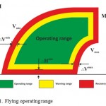 |
Figure 1: Flying operating range |
During its operation the OFSS evaluates information on the external and internal environment and predicts situation evolution. When the prediction shows that FV flight parameters are outside of the operating limits, OFSS generates solutions and provides recommendations to minimize adverse effects. If the crew is taking the right actions (in accordance with the FCOM), the OFSS does not interfere with control but provides piloting recommendations and promptings to the crew. In case the crew doesn’t respond, the OFSS generates necessary correction and control signals to the AP or ACS to parry a dangerous situation and stabilize the flight.
The OFSS algorithms consistently analyses signs of a dangerous situation. Each of the signs of certain accuracy Рdsi detects the presence of such situation. If the total accuracy reaches a predetermined threshold Рdsi > Рcs, the presence of such situation is ascertained. After this flight conditions are analyzed (aircraft motion parameters: altitude, speed, and aircraft attitude, remaining fuel (fuel rest), weather conditions, obstacles on a runway, deflections of control surfaces (rudder, ailerons and elevator), state of landing gear and the state of other units of the plane, etc.) and the recommendations to the crew are formed .
Indication of OFSS promptings and commands in different display formats
Indication of OFSS promptings and commands is issued for all display formats used in the onboard flight safety support system for different modes of operation. Figures 2, 3 and 4 show examples of such display.
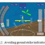 |
Figure 2: Avoiding ground strike indication |
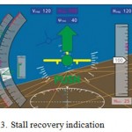 |
Figure 3: Stall recovery indication |
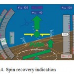 |
Figure 4: Spin recovery indication |
promptings and commands are displayed on the multi-screen display for the pilot in the respective display formats:
- a) director commands, showing the difference between the current and desired trajectory control parameters: Dnz – difference in longitudinal g-force (g-load) and Dϕ – difference in bank angle;
- b) given positions of the throttle l;
- c) single commands “Max” (Maximal) or “Idle”;
- g) Hdang – dangerous height in the mode of recovery from dangerous heights.
The OFSS also envisages output of different voice warnings and commands to the pilot by voice informant from «Bitching Batty», including:
- “Too low altitude, remove bank, pull up!”;
- “Left avoiding! Obstacle!”;
- “Too low (high) speed, increase (turn off) thrust, decrease pitch (pull up)!”;
- “Stall. Push the control stick”;
- “Spin. Push the control stick. Pedals left/right/neutral”;
- “Flaps up/Flaps down \ Retract/Extend landing gear”;
- and other voice messages.
In case the determined conditions are those under which it is impossible to recover FV from a dangerous situation and in case of a possible catastrophic outcome the command must be given or automatic activation of the parachute rescue system must be carried out (if it is available on board of the aircraft).
Automatic mode of recovery from dangerous situations
If there is an autopilot (AP) onboard a light FV automatic control of surfaces (rudder, ailerons and elevator) and engine control lever (throttle) recovery from dangerous situations is carried out via the autopilot. During recovery from complex spatial positions, in case of speed loss and recovery from dangerous altitudes or obstacles collision, OFSS and AP communication is carried out through floating tracking computer of predetermined g-force nz rear and the given bank angle ϕ rear. At the same time OFSS generates the control signals in AP for the trimming mechanism of roll and pitch initiation. Control via the AP in the longitudinal channel is carried out according to the longitudinal overload nz rear and pitch rate q.
Control in the roll channel is carried out by bank angle ϕ and/or roll rate p. Floating control in roll and pitch channels is provided by the integral control law. The control signals are formed in a digital computer of AP trajectory control:
- nz rear is calculated in the longitudinal channel depending on the operation mode;
- ϕ rear is calculated in the roll channel (roll control is carried out through the roll channel);
- ϕ (t) and nz (t) are compared with ϕ rear и nz rear.
Signals Δϕ = ϕ (t) – ϕ rear and Δnz = nz(t) – nz rear serve as a basis for generating control signals supplied from OFSS to AP.
With automatic stall and spin recovery, automatic control of surfaces (rudder, ailerons and elevator) and throttle is also going through AP. At the same time connection between OFSS and AP is carried out through the computer which tracks floating of the given controls deviations, depending on the angle of attack, indicated airspeed, yaw rate and roll rate.
OFSS information support with the use of vision systems
As a means of increasing the safety level at a low altitude, an integrated onboard radar computer vision system (CVS) is included into the onboard system. CVS may include such primary information sensors as laser radar, millimeter-wave radar, a video camera, a visible range video camera and a thermographic camera. At the same time the radar is used to capturing hazardous situations involving the possibility of the aircraft getting into extremely adverse weather conditions, which include
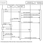 |
Figure 5: Structural units of the real time vision system software framework |
storm fronts, wind shear, clear air turbulence. Risk assessment is based on the results of data processing.
Set of hardware is designed to provide necessary data in different weather conditions. It is this opportunity that the devices, based on different physical principles and recording images of objects in the environment in several bands, provide. Information integration of these means provides a common computational and control system for collection, processing and display of data. Mathematical software of the system takes into account the specifics of physical phenomena and properties of objects in the appropriate band of radiant energy. On the other hand, this integration allows reducing the cost of the entire information management system due to its unification. The overall organization of algorithmic support and selected image processing algorithms do not depend on the nature of these images.
With reference to the problems of information support of mobile means and, in particular, FV, the essential feature is the need to operate in real time using the onboard computer equipment. These features impose strict requirements both to the actual algorithms of data collection and processing and to the process of developing the entire information management system of the aircraft. The basis of the integration technology is a software framework of real time CVS allowing quickly integrating different information data (Boguslavsky, & Sokolov, 2003). In this framework in the formalized form the object approach to the arrangement of algorithmic digital image elements collection and processing is presented (Figure 5 – class diagram of the software framework object of the real time CVS). The main components of the framework are parallel subsystems. There are several real time cycles – by the number of CVS operating modes.
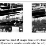 |
Figure 6: Example of results of synthesis two-band IR images (an electric train platform) with the two-dimensional histogram equalization (on the right) and with usual association (at the left) |
In particular, the framework includes:
- real time control system;
- debugging tools of individual components and algorithms;
- large library of algorithms for collecting and processing of visual data;
- automated calibration system of video cameras and stereo systems;
- algorithms for fields of vision with the data of satellite navigation systems GPS/GLONASS and geospatial data.
Algorithms operation in real time is provided by rational selection, integration, improvement of data (Sokolov, Kirilchenko, & Batanov, 2003; Sokolov, and Boguslavsky, 2011) and display of images of different spectral bands. An example of the algorithm for producing a synthetic image of the surrounding space is a synthesis algorithm of dual-band infrared images from two-dimensional histogram equalization (Kozlov, Sokolov, Solyakov, & Trenin, 2012) (Figure 6).
Conclusion
The achieved level of crew intellectual support and flight safety issue development in production of military aircraft, possibilities of modern onboard computing means and cockpit indication products, availability of tools that meet computer speed requirements , memory volume, power consumption performance, mass-dimensional and cost characteristics made for GA aircraft onboard equipment, make it possible to create flight safety onboard systems for small aircraft.
References
- Akhrameev, V. Goman, M., Merkulov, A., & Klumov, A. (1989). Automation of spin recovery of an aircraft using the method of resonant step-up. Proceedings of the Central Aerohydrodynamic Institute, 3370.
- Akhrameev, V., & Goman, M. (1989). Synthesis of resonant step-up algorithms of aircraft angular motion for spin recovery. Research of some problems of aerodynamics and flight dynamics of the aircraft.
- Akhrameev, V, & Goman, M. (1991). Automation of aerobatic aircraft spin recovery. Technique of Air Fleet, 3, 491.
- Akhrameev, V. (1998, November 16). Critical Flight Regimes and Dangerous Flight Conditions Investigation, Testing Approach, Diagnostics and Problem Solution – Workshop in Flight Simulator and Critical Flight Regime Investigation. Department of Aeronautical Engineering Chung Cheng Institute of Technology, Taoyuan, Taiwan, Republic of China.
- Report of the Interstate Aviation Committee (IAC). (2008). State of flight safety in the GA of “Agreement on Civil Aviation and the airspace use” States Parties in 2008.
- Babichenko, A., & Zemlyaniy, E. (2014). On substantiation of requirements to onboard expert systems of crew intellectual support. Aerospace Instrument Engineering, 12.
- Shishkin, V. (2005). Flight safety and on-board information systems. Ivanovo: MIK publishing house.
- Boguslavsky, A., & Sokolov, S. (2003, July 27-30). Component Approach to the Applied Visual System Software Development. Processing of the 7th World Multiconference on Systemics, Cybernetics and Informatics (SCI 2003), Orlando, Florida, USA.
- Sokolov, S., Kirilchenko, A., & Batanov, A. (2003, July 27-30). Increase of Efficiency of the Mobile Robots with the Help of the Information System Intellectualization. Proceedings of the 7th World Multi-Conference on Systemics, Cybernetics and Informatics (SCI 2003), Orlando, Florida, USA.
- Sokolov, S., & Boguslavsky, A. (2011, March 27-30). Intellectual Images Processing for a Realtime Recognition Problem. the 2nd Intern. Multi-Conf. on Complexity, Informatics and Cybernetics (IMCIC 2011), Orlando, Florida, USA, Vol. II, 406-411.
- Kozlov, K., Sokolov, S., Solyakov, V., & Trenin, D. (2012). Synthesis of dual-band infrared images with a two-dimensional histogram equalization. Computer vision in control systems 2012. Collection of works of the scientific and technical conference “Computer vision in control systems – 2012”, Moscow, Space Research Institute of the Russian Academy of Sciences, 227-233.

This work is licensed under a Creative Commons Attribution 4.0 International License.


