

Manuscript accepted on : 05 November 2016
Published online on: --
Plagiarism Check: Yes
V. Prakash, P. Dinesh, V. G Sukumaran, A. Subbiya, P. Vivekanandhan and Sherin Banu
Department of Conservative dentistry and Endodontics, Sree Balaji Dental College and Hospital, Bharath University, Chennai- 600100, Tamilnadu, India.
Corresponding Author E-mail: drprakashmds@gmail.com
DOI : http://dx.doi.org/10.13005/bbra/2362

ABSTRACT: A correlation between the material composition and phase changes during cyclic fatigue of three different(K3, K3XF, HYFLEX CM) rotary instruments were studied using DSC (Differential Scanning Calorimetry) and ICP-OES (Inductively Coupled Plasma Optical Emission Spectroscopy). To determine the role of composition and phase changes present in different types of NiTi rotary instruments during cyclic fatigue. ICP-OES was done by mixing 0.5g of sample with 20 ml of 1:1 ratio of water and 98% sulphuric acid. Samples were then heated upto 250oC to dissolve and then they were made upto 100 ml by adding distilled water. The samples were sent in the ICP-OES machine, where the samples get converted into different ions of characteristic intensity, from which the compostion is determined. DSC was done by heating/cooling the sample at the rate of 10oC/min increase in temperature. The sample is first heated to +130oC from room temperature and then cooling down to -150oC to obtain the cooling curve and then heated back to +130oC to obtain heating curve. The number cycles to failure were tested by Universal Testing machine and results were tabulated. One way ANOVA and Tukey tests were used to analyze the data. Enthalphy of HYFLEX CM was found to be highest followed by K3XF enthalpy and K3 found to be having Least Enthalpy. Comparing time taken for fracture of HYFLEX and K3XF there was statistically significant difference. Within the limitation of this study, it may be concluded that HYFLEX is the preferred instrument of choice in curved canals due to its controlled shape memory and longer time for phase transformation.
KEYWORDS: HYFLEX; K3; Cyclic fatigue; phase change; Differential Scanning Calorimetry; Inductively Coupled Plasma Optical Emission Spectroscopy
Download this article as:| Copy the following to cite this article: Prakash V, Dinesh P, Sukumaran V. G, Subbiya A, Vivekanandhan P, Banu S. Correlation of the Material Composition and Transistional Phases During Stress, on Cyclic Fatigue of Three Different Ni-Ti Rotary File System. Biosci Biotech Res Asia 2016;13(4). |
| Copy the following to cite this URL: Prakash V, Dinesh P, Sukumaran V. G, Subbiya A, Vivekanandhan P, Banu S. Correlation of the Material Composition and Transistional Phases During Stress, on Cyclic Fatigue of Three Different Ni-Ti Rotary File System. Biosci Biotech Res Asia 2016;13(4). Available from: https://www.biotech-asia.org/?p=17408 |
Introduction
NiTi rotary instruments introduced by Walia et al (1988) have been a boon for cleaning and shaping of root canals, because of their relatively low elastic modulus demonstrating enhanced flexibility as compared with stainless steel hand instruments. NiTi alloy changes its crystalline structure during stress from its original austenitic phase to stress induced martensitic phase, and reverting back to austenitic phase when unloaded by property of superelasticity.
The major concern which restricts the usage of rotary instruments is the unpredictable separation of the instrument in the root canal. The main cause of instrument separation is the fatigue of the instrument. Fatigue may be- torsional or cyclic fatigue. Torsional can be to certain extent operator controlled but cyclic fatigue is beyond the control of the operator.
Cyclic fatigue occurs when the instrument is exposed to repeated cycles of compression and tension about the same point around a curvature. Niti instruments undergo multiaxial loading (ie) compression, tension and shear during preparation.
Of the many researches done the most viable outcome was the introduction of R phase (2008) and Controlled memory wires (2010), which they claimed to have better flexibility and fatigue resistance when compared to conventional NiTi wire.
The main objective of this study was to find out the role of composition and phase changes present in different types of NiTi rotary instruments during cyclic fatigue.
Materials and Methods
Inductively Coupled Plasma Optical Emission Spectroscopy
It is a type of emission spectroscopy that uses the inductively coupled plasma torch to produce excited atoms and ions that emit electromagnetic radiation at wavelengths characteristic of a particular element. The intensity of this emission is indicative of the concentration of the element within the sample.
The instruments were first cut using a diamond disc under water cooling into small pieces. The pieces were then weighed. Then 0.5g of the samples were taken in a beaker and mixed with 20ml of 1:1 ratio of water and 98% sulphuric acid. The samples were then placed in a stainless steel plate on an induction heater and heated at temperature of 250oC for dissolving the sample. 20-25 mins was taken to dissolve the sample. The samples were the left to cool down. Then 100ml of distilled water was added to the sample to increase the volume. Then the samples were placed in a vial and placed in the suction motor of the ICP-OES Machine (VARIAN 720 ES). The motor sucks in the sample and the samples were sprayed in the spray chamber which was converted into aerosol. When the aerosol reaches the torch flame it was separated into different ions that were captured by the detector. From the intensity of the captured ions the intensity is matched with the graph in the software that gives the desired element in the sample[Figure 1].
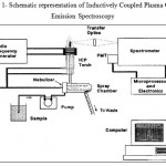 |
Figure 1: Schematic representation of Inductively Coupled Plasma Optical Emission Spectroscopy |
Differential Scanning Calorimetry:
The temperature program for a DSC analysis is designed such that the sample temperature increases linearly as a function of time. The reference sample should have a well-defined heat capacity over the range of temperatures to be scanned.
The samples are cut using diamond disc under water cooling into three segments of equal length. The samples are then subjected to DSC .The DSC analysis was conducted by DSC 200 F3 MAIA (NETZSCH, GERMANY) over a temperature range of -150oC to +130oC by using liquid nitrogen for cooling. For each analysis the specimen was placed in an aluminum crucible and secured with a lid with locking mechanism. Then using a sealing press a hole is punched on the surface of the lid. The DSC instrument consists of a platform on which the crucible is placed. The adjacent side of the platform an empty aluminum crucible is placed as control during temperature changes. The platform is connected to an heat flux sensor which detects the temperature changes. The specimen is heated first upto +130oC, then cooled down to -150oC to obtain the DSC curve and subsequently heated back to +130oC to obtain the heating curve. The linear heating or cooling rate was at 10oC/min and during the analysis dry nitrogen was purged at 50mL/min. The plots were analyzed using the Proteus software to obtain the temperatures.
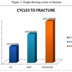 |
Figure 2: Graph showing cycles to fracture |
Cyclic Fatigue
The cyclic fatigue testing is done in a steel block simulated to have a 45 degree curvature and 5mm radius. The hand piece (16:1 reduction gear) was attached to the upper arm of the universal testing machine and the steel block was fitted onto the lower arm. The files were then guided into the ‘V’ notch of the block with, load of 10psi (10gm) and pecking distance of 3mm. 16:1 reduction gear hand piece was used. The torque was placed at 3 Ncm and Rpm was according to the manufacturer’s instructions. K3, K3XF- 350 rpm and Hyflex CM- 450 rpm.
Copious amounts of EDTA (glyde) was placed inside the canal. All instruments were rotated until fracture occurred. Time to fracture was recorded using the computer. The number of rotations to fracture was calculated by multiplying time taken to fracture and rotations per minute.
The fracture was easily detected as the tip of the instrument was visible. Eight instruments were tested for each group. Mean values are calculated. Statistical analysis is done.
Differential Scanning Calorimetry:
The fractured instrument tips are then subjected to DSC as before. The graph isattained.[Figure 3]
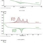 |
Figure 3: DSC Curves of K 3, K3 XF, HYFLEX CM |
Results
The composition of the files is shown in Table 1. ANOVA AndTukeys’ test were used to analyse enthalpy, cycles to fracture[Table 2], and time taken to fracture. Enthalphy of HYFLEX CM was found to be highest followed by K3XF enthalpy and K3 found to be having Least Enthalpy of which is Statistically significant ( p value <0.05) ANOVA. Comparing Entalphy of HYFLEX and K3XF there is Statistically significant difference between HYFLEX and K3XF (p value 0.000). Comparing Entalphy of K3 and K3XF there is Statistically significant difference between K3 and K3XF (p value 0.000) . Comparing time taken for fracture of HYFLEX and K3XF there is Statistically significant difference between HYFLEX and K3XF(p value Significant <0.05 ) .Comparing time taken for fracture of K3 and K3XF there is no Statistically significant difference between K3 and K3XF (p value 0.883). Comparing cycle taken for fracture of HYFLEX and K3XF there isStatistically significant difference between HYFLEX and K3XF.(p value Significant <0.05 Comparing cycle taken for fracture of K3 and K3XF there is no Statistically significant difference between K3 and K3XF [Table 2& 3][Figure 2].
Table 1: Composition of the Files
| ELEMENTS
(WT %) |
K3 | K3 XF | HYFLEX CM |
| NICKEL
|
58.29 | 56.37 | 52.34 |
| TITANIUM
|
38.17 | 40.89 | 44.30 |
| SILICON
|
2.43 | 1.92 | 2.38 |
| ALUMINIUM
|
0.47 | 0.29 | 0.42 |
| ZINC
|
0.40 | 0.37 | 0.39 |
| COPPER
|
0.011 | 0.033 | 0.068 |
| CADMIUM
|
Bdl* | Bdl* | Bdl* |
| OTHERS
|
0.13 | 0.12 | 0.10 |
Table 2: Cycles to fracture
| GROUPS | K3 | K3XF | HYFLEX |
| A | 522.58 | 929.16 | 1350.75 |
| B | 524.32 | 935.54 | 1357.5 |
| C | 525.48 | 930.32 | 1353.75 |
| D | 530.12 | 926.84 | 1349.25 |
| E | 531.28 | 927.42 | 1341.75 |
| F | 521.42 | 928 | 1352.25 |
| G | 523.16 | 930.9 | 1351.5 |
| H | 526.64 | 932.06 | 1355.25 |
Table 3: Enthalpy Changes (A H)
| SAMPLES | K3 | K3XF | HYFLEX CM |
| UNPREPARED SAMPLE | 2.265J/g | 14.92J/g | 18.69J/g |
| PREPARED SAMPLES | |||
| A. | 0.010J/g | 7.558J/g | 13.61J/g |
| B. | 0.133J/g | 9.885J/g | 13.75J/g |
| C. | 0.145J/g | 8.258J/g | 12.40J/g |
| D. | 0.160J/g | 9.245J/g | 12.39J/g |
| E. | 0.150J/g | 8.582J/g | 12.59J/g |
| F. | 0.170J/g | 9.254J/g | 12.35J/g |
| G. | 0.165J/g | 8.785J/g | 13.25J/g |
| H. | 0.158J/g | 7.675J/g | 13.50J/g |
Discussion
Nickel titanium endodontic files are particularly helpful in sucessful shaping of curved root canals demonstrating greater flexibility and superior resistance in bending and torsion as compared to stainless steel instruments. The nickel titanium alloy composition is based on the equiatomic intermetallic compound and these instruments are entirely fabricated by a machining process, in contrast to the twisting of tapered wire blanks that has been used for the traditional manufacturing of stainless steel instruments. (6)
The structural fatigue relates to the microstructure damage that accumulates during cyclic loading which eventually loads to fatigue failure.(7) Cyclic fatigue is known to exaggerate in a canal with a shorter radius of curvature and occurs when the instrument is exposed to repeated cycles of compression and tension about the same point around a curvature.
In order to overcome this drawback constant research with newer methods and advanced technologies of manufacturing rotary instruments are being carried out. Currently much focus is being done on the phase transformation of Niti alloys. It is believed Austenite is tranformed to Martensite during loading and reverts back to Austenite while unloading. This transformation is reversible during clinical use because the Niti alloys have Transition Temperature Range (TTR) lower than the mouth temperature(4,8). A reversible solid phase transformation known as Martensite transformation is the primary force behind shape memory alloys. The transformation from one form of crystalline structure to another during stress creates a mechanism by which shape changes is refered to as Superelasticity(8,9). This effect permits the stress value to remain fairly constant up to a long range of defelection.(10)
NiTi alloys have an inherent capacity to undergo phase transformation within the matrix from austenite (parent phase) to martensite (daughter phase) with the application of temperature. This property is referred to as Shape memory effect.(11,8)When the alloy is cooled through critical transformation temperature range (TTR) change in the crystalline structure occurs. This deformation can be reversed to original parent phase by heating leading to shape memory effect.(11) The Transition Temperature Range of Niti can further be altered by composition, method of fabrication and heat treatment of the alloy. Direct transformation from Austenite and Mastensite includes an intermediate structure called ‘R phase’.(4,12)
The crystal sturcture of NiTi alloys at high temperature is a stable body centered cubic lattice which is refered to as Austenite phase or Parent phase.(8) The austenite phase is stable at high temperature and martensite is stable at low temperatures. Austenite, the stronger phase of shape memory alloys, occurs at higher temperatures with a simple cubic structure. In martensitic phase the atoms orient themselves in rows. That are tilted left or right, this phenomenon called as twinning as atoms form mirror images of themselves or twins(8,13). Under stress the martensitic twins, de twine towards opposite side, causing deformation. Nitinol has a property that when it is cooled throught critical transition temperature the alloy shows lower modulus of elasticity.(8,14)
The ‘R’ phase transformation is characterized , with appearance of large super lattice reflections along parent phase. Although ‘R’ phase is said to be rhombohedral in structure, with decreasing temperature and stress they were found to be as cubic lattice along diagonal direction.(15)
New technology that is recently introduced is the controlled memory wires(CM). These instruments have higher flexibility and fracture resistence superior to conventional Niti rotary instruments made from superelastic wires. CM wires were nearly 300% to 800% more resistant to fatigue fracturewhen compared to conventional Niti instruments.The property of superelasticity and shape memory are strongly due to the heat treatment procedure done during manufacture.(16) These wires consist of deformed and microtwinned martensite, austenite and R phase. They showed superior resistance to fatigue compared to regular SuperElastic wires due to better reorientation capability of martensitic twins because of the lower symmetry of monoclinic crystal structure of martensite than the cubic crystal stucture of austenite(4).
The custom made steel block used in this study has proved to provide better standardization with consistent result by previous authors. In our study 45o angle has been chosen since it is well within the average of canal curvature to be clinically relevant.(5)
As pecking distances increased the time to failure increased, as a longer pecking interval gives a longer time interval before it once again passes through a higher stress area. The longer the pecking movement better distribution of cyclic fatigue along the length of the instrument rather than at the point of bending, thereby the chosen pecking distance was 3mm(17).
DSC testing is one of the many methods used to determine the transformation temperature of NiTi alloys. DSC is a thermal method that measures the changes in heat flow which is associated with the austenitic and martensitic phase transformations through a controlled heating /cooling cycle.(19)DSC testing was carried out by heating the samples to +130OC then by cooling down to -150OC. This high temperature variation helps in recording the entire transformation temperature of the sample.(11) In this method the difference in thermal power supplied to test specimen and inert control specimen heated at the same rate is measured very accurately. The scanning rate is recorded as a function of temperature to yield the thermogram. The start and finish temperatures are determined by tangent lines.(4). Structural transformation in NiTi alloys are revealed as endothermic peaks on heating DSC curve and exothermic peaks on cooling DSC curves, and information is obtained about the temperature ranges and enthalpy changes for phase transformation. For NiTi alloys DSC indicates which of three phases ( martensitic NiTi, ‘R’ phase, austenitic NiTi) will be present at given temperature.(19)Although X Ray Diffraction analysis is another complimentary method to investigate structure of NiTi, but this method reveals structure within approximately 15 microns of surface whereas DSC provides phases present in overall bulk of specimen. (19).
ICP-OES (Inductively Coupled Plasma Optical Emission Spectroscopy) is a type of emission spectroscopy that uses the inductively coupled plasma to produce excited atoms and ions that emit electromagnetic radiation at wavelengths characteristic of a particular element. The intensity of this emission is indicative of the concentration of the element within the sample. Composition was determined by ICP-OES by dissolving the samples which reduces the risk of any impurities in the instrument that might hinder from observing the exact composition of the instruments, giving an advantage over other methods of determining the composition.(3)
The Nickel Titanium root canal instruments contain mainly of nickel and titanium. They are also substituted with other elements like silicon, aluminum, copper, cadmium, zinc and other trace elements.
The main role of nickel is the increase in austenitic finish temperature (Af) leading to longer time for phase transformation. The amount of nickel present in the alloy increases the amount of energy needed to result in phase transformation (enthalpyH) (6). The addition of 3rd alloying element is also beneficial for tailoring transformation temperatures and mechanical properties for specific application. When Copper is added as substitute for Nickel, the transformation temperature become less sensitive to composition as compared with binary NiTi alloy.(20) The main advantage of copper is that it helps in lowering the deformation stress of martensite formed during loading. The additive Copper makes casting, processing and controlling shape memory properties easier.(21) The aluminum content might be due to the final assembly of the files during which the machined files is yanked under pressure in the aluminum made shank.(22)
In the present study the rotary root canal instruments were selected to compare a conventional NiTI instrument with a heat treated instrument and a newer controlled memory type of NiTiinstrument. Group A was K3 which is a conventional NiTi instrument. K3 was used as control group since it was made from conventional NiTi wire, and it is been used in day today clinical practice. It has radial land with slightly positive rake angle and non cutting tip. Also K3 is said to have variable helical angle and varying core diameter decreasing towards the shank.(22,23,24)
K3 XF had similar features as of K3 files. But it was claimed by the manufacturer of ‘R’ phase heat treated and had more flexibility when compared to K3 and other conventional NiTI rotary instruments.(15)
Hyflex CM being controlled memory wire is aid to have 300- 800% more flexibility. They consisted of triangular cutting blank.(16) They have an Variable pitch that helps in improved flexibility, increasingly wider flutes provides efficient debris transportation and prevents file from “screwing” into the canal. Also the absence of radial lands shows increased flexibility and minimized torque.
K3XF was found to be more resistant than K3 suggesting to the fact that this might be due to the ‘R’ phase treatment it undergoes during manufacture even though the file structure is similar. Young’s Modulus (stiffness) of ‘R’phase is lower than that of martensite an thus an instrument in ‘R’ phase would be more flexible.(4). R phase forms as an intermediate phase during forward transformation between martensite to austenite and vice versa.(14)
Group C Hyflex had statistically significant higher cycles to fracture as compared to other two groups as evident in Table.The DSC results showed that Hyflex had Af temperatures much higher than that of oral temperature than the other 2 groups.(25) Hyflex had a lower weight percentage of Nickel content than the other two file groups. The lower the percentage of Nickel content higher is the austenitic finish temperature due to decrease in the transformationso it requires more stress to get converted from austenite to martensite resulting in more cycles to fracture than other two groups. Also the lower percentage of Nickel decreases the yield strength of the austenite leading to increase flexibility, which might be the reason for higher cycles to fracture for Hyflex. Titanium substituted for any element in the alloy results in increase in transformation temperature.(26). This was evident from the DSC plot of Hyflex having maximum Aftemperature (44oC) which is much higher than intra oral temperature suggesting that Hyflex took longer time under stress for phase transformation from austenite to martensitic when compared to other two instruments.
According to Table.1 percentage of Copper is significantly higher in Hyflex when compared to other two groups. More the percentage of Copper the Stress Hysteresis becomes smaller,(20) which means more mechanical energy is required for phase transformation. This also explains the reason for higher cycles to fracture for Hyflex. Also Hyflex having a higher Af temperature it requires more stress to get converted from austenite to martensite resulting in more cycles to fracture than other two groups.
From the DSC plots it is evident that the enthalpy changes in Hyflex (18.69J/g) were much higher than that of other 2 groups, suggesting that it is both austenite and martensite at room temperature.(25). Freshly formed martensite is brittle and only tempered martensite is acceptable for endodontic instrument for clinical usage.(26)
Hyflex exhibited the maximum resistance and time taken to fracture as evident in Table3. From this view Hyflex instrument can be suggested in use in curved canals because of its better resistance to fatigue which might be due to the triangular cutting blank that increases flexibility. Also the presence of Variable pitch and absence of radial land helps in more resistance.
Conclusion
Hyflex seems to perform better in curved canals, due to the lower percentage of nickel leading to longer time for phase transformation due to higher Af temperature.
Higher percentage of Copper in Hyflexhelps in decreasing the Hysteresis resulting controlling shape memory effect.
The Controlled Memory technology in Hyflex having tempered martensitic phase seem to perform better as compared to freshly formed martensite which is brittle.
As Hyflex has triangular cutting blank with no radial lands, they appear to be more flexible with least resistance in cleaning and shaping of curved canals as compared to other groups.
Within the limitations of this study Hyflex may be preferred as instrument of choice for curved canals.
References
- Michael Larsen, Ikuya Watanabe, Cyclic Fatigue Analysis of A new Generation of Nickel Titanium Rotary instruments, J. Endod 2009;35( 3):401- 03.
CrossRef - C M Bejoy Mony, B Hemasathya, Suresh Mitthra. Perception and pro-prioception in relation to masticatory act. Biomedical and pharmacology journal 2015;Special issue (8):149-154.
- Sudha, V.G.Sukumaran, Jaya Narasimha Bharadwaj. Comparative evaluation of the effects of two concentrations of EDTA at two different pH and time periods on root dentin – An in-vitro study. J Conserv Dent 2006; 9(1): 36-42.
CrossRef - Kuhn G, Jordan L, Fatigue and Mechanical properties of Nickel-Titanium endodontic instruments. J.Endod 2002;28( 6): 716-20.
CrossRef - Pruett JP, Clement DJ. Cyclic Fatigue testing of Nickel- Titanium rotary instruments. Endod 1997; 23( 2): 77-85.
CrossRef - Hani F, Thakib AL, Quantitative and Qualitative Elemental analysis of different Nickel- Titanium rotary instruments by using Scanning Electron Microscopy and Energy Dispersive spectroscopy, J. Endod 2008;34( 1): 53 -55.
CrossRef - Plotino G et al, A Review of cyclic fatigue testing of Nickel Titanium rotary instruments. J. Endod 2009: 35: 11.
CrossRef - Thompson SA, An overview of Nickel Titanium Alloys used in dentistry. Int. Endod J 2002; 33: 297-310.
CrossRef - Roh JH et al, Thermo mechanical behaviours of NiTi shape memory alloy ribbons and their numerical modeling, Mechanics of material 2010;42: 757-73.
CrossRef - J Prabhakar, Alagarsamy Venkatesh, Gold Pearlin Mary. Accuracy of three different electronic apex locators – A pilot study. Biomedical and pharmacology journal 2015;Special issue (8):335-339
- Georgia B , KonstantinosChrissafis, SEM observations and Differential Scanning Calorimetry studies of New and Sterilized Nickel- Titanium endodontic instruments, J. Endod 2006; 32: 675- 79.
CrossRef - Sundaresan Balagopal, VirudhachalamGanapathy Sukumaran, Vandana James. Effect Of Electro Magnetic Field (Emf) On Dental Amalgam And General Health. Biomedical and pharmacology journal 2015;Special issue (8):625-629.
- Parashos P, Messer HH, Rotary NiTi instrument fracture and its consequences, J. Endod 2006; 32( 11): 1031-43.
CrossRef - Sittner P, Landa M, R-phase transformation phenomena in thermomechanically loaded NiTi polycrystals. Mechanics of Materials 2006; 38: 475-92.
CrossRef - Hemasathya, Paramasivam Vivekanandhan, CM Bejoy Mony. Nerve Injuries During Root Canal Treatment:A Review. Biomedical and pharmacology journal 2015; Special issue (8):155-160.
- YaShen et al, Effect of environment on Fatigue Failure of Controlled memory wire Nickel – Titanium rotary instruments. J. Endod 2012;38( 3):376 – 80.
CrossRef - Li UM, Lee BS, Cyclic fatigue of Endodontic Nickel- Titanium roatary instruments: Static and Dynamic tests, J. Endod 2002;28(6):448-51.
CrossRef - Yao JH, Schwartz SA, Cyclic Fatigue of three types of rotary Nickel – Titanium files in a dynamic model. J. Endod 2006; 32( 1): 55-7.
CrossRef - Brantely WA et al, Differential Scanning Calorimetric Studies of Nickel Titanium Rotary Endodontic instruments. J.Endod 2002;28(8):567-72.
CrossRef - Hemasathya, CM Bejoy Mony, Venkatachalam Prakash. Recent advances in root end filling materials: A review. Biomedical and pharmacology journal 2015;Special issue (8):219-224
- Prabhakar, Radhakrishnan Mensudar, Nagarajan Geethapriya. Cleaning efficiency of Triphala (An Indian herbal medicine) and green tea polyphenol used as irrigants on removal of smear layer: A SEM study. Biomedical and pharmacology journal 2015;Special issue (8):303-307.
- Subbiya, CV Subba Rao, RG. Balaji. Effect of disinfectants and glass bead size on efficacy of glass bead sterilizer. J Conserv Dent 2005; 8(3):23-31.
CrossRef - Abilash, Mensudar, P.Vivekanandhan, A. Subbiya, V.G.Sukumaran.. Cutting efficiency, surface change and hardness: EZ-fill safe sider instruments vs K-files. Indian Journal of Multidisciplinary Dentistry 2011; 1(2):110-114.
- Bahia MGA, Melo MC, Influence of Cyclic torsional loading on the fatigue resistance of K3 instruments. Int. Endod J 2008; 41: 883-91.
CrossRef - Otsuka , X. Ren , Physical metallurgy of Ti–Ni-based Shape memory alloys, Progress in Materials Science 2005;50 : 511–678.
CrossRef - Kim TO, Cheung GSP, Stress distribution of three NiTi rotary files under bending and torsional conditions using a mathematic analysis, IntEndod J 2009; 42(1): 14-21.
CrossRef

This work is licensed under a Creative Commons Attribution 4.0 International License.


