

Manuscript accepted on : 10 January 2016
Published online on: 25-07-2016
Zhanar Zhakupova, Aleksandr Yakovlev, Tlektes Yespolov, Graziano Ghinassi, and Yerbol Sarkynov
Kazakh National Agrarian University, pr. Abaya, 8, , Almaty, 050010 Kazakhstan.
DOI : http://dx.doi.org/10.13005/bbra/2293

ABSTRACT: The work discusses the processes in hydraulic packer with ejector upon pipeless water lifting from wells, determination of engineering and technical parameters, verification of reliability and correction of theoretical backgrounds for the processes: fixation of hydraulic packer with electrical submersible pump in well, compression of hydraulic packer with well casing wall and pinching оf the packer detwisting mechanism in well; adjustment of major parameters of substantiated typical sizes of hydraulic packers with ejector during their experimental study. The work is based on patent reviews, theoretical considerations, calculations, procedural and experimental approaches.The work presents the results of performed experimental study of the processes in hydraulic packer with ejector upon pipeless water lifting from wells by means of electrical submersible pump: fixation and compression of hydraulic packer in well, pinching of detwisting mechanism. The following parameters are experimentally determined: coefficient of packer local resistances, friction coefficient of rubber-coated roller along steel pipe, required minimum excessive water pressure in packer for expansion of sealing ring, required force for packer shimming. Experimental study of the processes in hydraulic packer has confirmed reliability of the assumed mathematical backgrounds, they will be applied in development of their required typical sizes. Therefore, the positive experimental results of study of innovative patented hydraulic packer with ejector can be applied for marketing of devices with required typical sizes for electrical submersible pumps in order to implement efficient water lifting both for general purpose water supply and for melioration, thus reducing metal consumption by 2-3 times in comparison with the existing technology of water lifting (using pipes), as well as operational expenditures for assembling works, increasing operation lifetime of well casing, excluding water pollution and well clogging, improving power indices of pump facility.
KEYWORDS: pipeless water lifting; underground water; well; electrical submersible pump; hydraulic packer; laboratory specimen; experimental study; running process; process variable
Download this article as:| Copy the following to cite this article: Zhakupova Z, Yakovlev A, Yespolov T, Ghinassi G, Sarkynov Y. Experimental Study into The Processes Running in Hydraulic Packer upon Pipeless Water Lifting from Wells by Means of Electrical Submersible Pump. Biosci Biotech Res Asia 2016;13(3). |
| Copy the following to cite this URL: Zhakupova Z, Yakovlev A, Yespolov T, Ghinassi G, Sarkynov Y. Experimental Study into The Processes Running in Hydraulic Packer upon Pipeless Water Lifting from Wells by Means of Electrical Submersible Pump. Biosci Biotech Res Asia 2016;13(3). Available from: https://www.biotech-asia.org/?p=15059 |
Introduction
Nowadays in Kazakhstan autonomous water supply of agricultural consumers both for domestic needs and for irrigation of land plots, especially in southern regions, is provided due to underground waters from specially developed wells, mainly by means of electrical submersible pumps.
However, the existing technology of water lifting from wells by means of electrical submersible pumps requires for water lifting pipes, their weight per one pump facility is 500…1000 kg, it requires high operational expenditures for assembling procedures.
Application of the challenging technology of pipeless water lifting (by well casing) using packers of various designs installed on pump delivery pipe, separating pump suction and delivery portion in the well, makes it possible to reduce specific metal consumption by 2…3 times, to improve power indices of pump facility, to reduce significantly operational costs of assembling activities, to increase operational lifetime of well casing, to exclude water contamination and well clogging.
However, implementation of pipeless water lifting into water supply and melioration is restricted due to the unavailability of required typical sizes of packers for electrical submersible pump as a consequence of insufficient theoretical and experimental researches of technological processes occurring in packer. Thus, development of the required typical sizes of hydraulic packers and appropriate researches, including experimens, with electrical submersible pumps intended for pipeless water lifting in water supply and melioration is an urgent issue.
Review of existing works
While investigating into resource saving technology of pipeless water lifting from wells (by well casing) by means of electrical submersible pumps using hydraulic packers, great attention was paid to experimental studies both of technological process and of processes running in packers [1-8].
Numerous works are devoted to development of designs, theoretical and experimental studies of pipeless water lifting from wells with packers for electrical submersible pumps of domestic and foreign researchers: A. G. Zhelobovsky, V.S. Usenko, A. D. Gurinovich, V. D. Gladkov., M. A. Lavrov (1975-1990) [9-16], A. I. Fabrikov, A. A. Sil’chenko, V. M. Kostyukevich., R. S. Ariel’. (1982-1985) [13,14,15], V. N. Fisenko, M. M. Trusov, V. Ya. Rait (1985-1994) [16,17,18], S. V. Morozov, A. A. Pevzner, Yu. P. Kalmykov, L. A. Kolodyuk, S. S. Poleshchuk(1986-1990) [19], A. A. Yakovlev, A. B. Konyrbaev ( 1986-2000) [1-3,20-23], V. D. Krapivin [24], E. Sarkynov, Zh. Z. Zhakupova [4, 5, 6].
In 1975-95 such companies as TsNIIKIVR (Minsk, Byelorussia) [9-16], Soiuzgiprovodkhoz (Moscow), and YuzhNIIGiM (Novocherkassk, Russia) [16] carried out researches on development of packers for electrical submersible pumps intended for pipeless water lifting from wells with the conventional diameter of 8, 10 and 12 inches. Packer sealing unit is made of self-compressing rubber collar (Fig. 1, a and b), and fixing mechanism in the form of bars with conic grooves, they are driven mechanically by means of rods used for lowering of packer with electrical submersible pump. Experimental specimens demonstrated positive results.
Kazakh R&D Institute of water management (1980-2000, Kazakhstan) [18-20] performed researches of pipeless water lifting and developed packers for electrical submersible pumps of three typical sizes for wells with conventional diameter of 8, 10, and 12 inches intended for melioration. Packer (Fig. 1 c ) is comprised of the body in the form of pipe connected to the pump delivery pipe, equipped with fixing mechanism, made of shims and sealing collar, flanged to the pipe and installed in cylindrical socket moving by the pipe. Fixation and preliminary compression of packer in well is performed mechanically by means of rods used for lowering of packer with electrical submersible pump into well. The project was finished by production of experimental batch of packers, positive results were achieved upon implementation of the devices in Kazakhstan melioration.
 |
Figure 1: Layouts of well known packers for electrical submersible pumps for pipeless water lifting. 1 – pump; 2 – packer; 3 – well casing; 4, 5 – handling and fixing mechanisms. а) YuzhNIIGiM design; b) TsNIIKIVR design; c) KazNIIVKh design. |
In 1986-90 NIS Rovno Pedagogical Institute [21] on contractual terms with Gosagroprom of Kazakhstan performed researches and development of packer for electrical submersible pump: UBV Goryn (Fig. 2, a) for water lifting by well casing with the diameter of 6 inches. sealing portion of the design was the same as in the design of Kazakh R&D Institute of water management: sealing collar, flanged to the pipe and installed in cylindrical socket moving by the pipe. However, some innovations were applied, aimed at simplification of disassembling activities (decrease in detachment of the collar), by means of varying height of socket side wall contacting with the collar. Experimental specimen was manufactured, demonstrating positive results.
NPO Kazselkhozmehanizatsiya (KazNIIMESKh) (1986-2000, Kazakhstan) [1–3,20–23] performed study of pipeless water lifting including development of three typical sizes of hydraulic packers for electrical submersible pumps, Grade ETsV for wells with conventional diameter of 5, 6, 8 inches for pasture water supply. A distinctive feature of the packer design (Fig. 2, b) for pipeless water lifting includes sealing portion in the form of two alternatively operating sealing collars, installed in the body with axial hole, which is fixed to the pump delivery pipe. The packer is equipped with fixing, detwisting and rope handling interconnected mechanisms, and sealed well head with outlet connection. The project was finished in 1997 by development of experimental specimens, state commissioning tests with UPG-168М typical size for 6-inch wells, and recommendations for their commercial production.
Among other designs the inflatable packer by V. D. Krapivin [24] is of interest (Fig. 2, c), USSR Authors’ certificate No. 252867, however, data on its development are unavailable.
 |
Figurer 2: Layouts of well known packers for electrical submersible pump for pipeless lifting. 1 – pump; 2 – packer; 3 – well casing; 4, 5 – handling and fixing mechanisms a)design of NIS Rovno Pedagogical Institute; b) design of NPO Kazselkhozmehanizatsiya; c) design by V. D. Krapivin. |
Scope of researches
Therefore, the studies were aimed at pipeless water lifting by means of electrical submersible pump and proprietary packer designs with substantiation of parameters; however, no investigations were carried out with regard to processes in the packers and no typical sizes of packers were developed with the aim of efficient implementation for pasture and general purpose water supply and melioration.
No investigations were performed with packers with ejector, involving water intake by the action of vacuum generated in ejector, with subsequent improvement of power indices of pump facility: increase by 20-30 % in comparison with the existing parameters of water lifting and efficiency of pump facility.
Objectives of the study
The work is aimed at investigation into the processes in hydraulic packer upon pipeless water lifting from wells, verification of reliability and adjustment of theoretical assumptions for the processes: fixation of hydraulic packer with electrical submersible pump in well, compression of hydraulic packer with well casing wall and pinching of packer detwisting mechanism in well; adjustment of main parameters of required typical sizes of packers upon experiments.
In Kazakh National Agrarian University (2011-2014, Kazakhstan) [7] we carried out study aimed at improvement of pipeless water lifting in order to increase efficiency of utilization of underground waters in the system of general purpose water supply and melioration.
Flowchart of pipeless underground water lifting was developed and adopted for instigations with innovative hydraulic packer equipped with ejector, providing 20-30 % increase in supply and efficiency of pump facility in comparison with the existing analogues.
General layout of pipeless water lifting from wells by means of electrical submersible pump using the innovative hydraulic packer with ejector is illustrated in Fig. 3.
 |
Figure 3: Flowchart of pipeless water lifting from wells by means of electrical submersible pump using new hydraulic packer with ejector. |
The following notations of process variables of pipeless water lifting and technical parameters of hydraulic packer are applied in Fig, 3: H is the water lifting height; Hp is the pump head; Q,QPF is the flow rate of pump and pump facility;d0, Dp, Dw, dR are the diameter of packer through hole, the packer outer diameter, the well internal diameter and the diameter of rubber-coated roller of detwisting mechanism, respectively; ∂S, ∂R are the rod lengths of fixing stop and double-armed lever of detwisting mechanism; β, α are the vertical slope angles of fixing stop and double-armed lever of detwisting mechanism; TSH, TN are the shimming forces and normal pressure, acting on the fixing stop; TT, TR are the forces of tension and retraction of the packer sealing ring; , are the forces of hydraulic pressure acting on the packer and detachment upon packer disassembling; P∏ is the excessive water pressure in the sealing ring; Rg, Tdet are the width, height and thickness of the sealing ring; br, hr, δr is the stroke of back-pressure valve; mp, mp are the weights of packer and electrical submersible pump, respectively.
In order to achieve the required objective we revealed the most significant factors influencing on the processes in hydraulic packer in the form of functional and analytical equations, the results are given on determination of main process variables of pump facility H, HP, N, ηH, ηPF = f (Q)with electrical submersible pump ETsV6-10-80 in combination with hydraulic packer with ejector upon water lifting via well casing and pipes [5, 6, 7]:

the main analytical dependencies of processes in hydraulic packer with ejector upon pipeless water lifting from wells in order to verify their reliability:
![]()
1) forces of hydrodynamic pressure Rg, shimming Ts and normal pressure TN, acting on packer and packer fixing stop:

2) tension forces TT of sealing ring of hydraulic packer and excessive water pressure PP in packer in dynamic operation mode:

checking of provisions of reliable fixation
![]()
checking of provisions of operation of packer detwisting mechanism in terms of interrelation of friction forces T’FR of pressing rollers and force TR of reactive torque upon pump starting
![]()
determination of shimming (detachment) force Tdet upon packer disassembling and comparison with theoretical value
![]()
where Pπmax is the maximum excessive pressure in the packer, kPa; mfris the spefici weight of rope of handling mechanism, kg/m; is the water lifting height (rope length), m;
determination of disassembling force of packer with electrical submersible pump and comparison with theoretical value
![]()
where , mπ, mH, mK are the weights of packer, pump, and rope, respectively, kg; ТN1 is the force of normal pressure on pressing roller of detwisting mechanism, N; fnep is the friction coefficient of rubber-coated roller along steel pipe; is the number of rods of detwisting mechanism.
Experimental
Procedures
All experiments were carried out by single factor method. The head range of electrical submersible pump ETsV 6-10-80 equaled to Hp= 20 m; 30 m; 50 m; 70 m; 80 m; 90 m. The diameter limits of well casing were DCK=152 mm and 203 mm.
The head of electrical submersible pump Hp was varied by throttling at the outlet of take-off connection of sealed head of bench well casing by means of valve according to pressure gauge. The internal diameter of well casing DCK was varied by insertion pipe.
While testing the following measurements were made for at least three times according to known procedures [23-30]: visually — flow rate of pump facility QPF by volumetric method using measuring tank and stopwatch; using records on oscilloscope and visually — readings of pressure sensors and reference gauges on packer inlet and outlet (in bench well casing — in the plane of packer outlet); using records on oscilloscope readings of force sensor installed in well casing wall in the contact area with packer fixing stop in order to measure acting force of normal pressure ТΝ.
The experiments were performed in the following sequence. Packer parameters were determined and, varying pump head HP in preset intervals, visual measurements and records of oscilloscope readings were carried out.
Fixation and compression of packer upon combined operation with pump were studied by oscillograms recorded by oscilloscope.
Detwisting and handling of packer with pump were studied upon individual experiment, where normal pressure on the roller T1N of detwisting mechanism, lateral force T1N, ffr rolling force T1N fnep, reactive torque upon starting of pump electric motor МR and shimming force Tofr of packer with pump were measured by dynamometer.
The acquired experimental data were processed and analyzed by known procedures [30-40]. The obtained experimental data were applied for determination of process variables according the following equations [2,7]:
Pump facility flow rate

where
Vt is the lifted water volume per experiment, m3; ti is the time of measurement of lifted water volume per experiment, s; m is the number of experiments.
![]()
where k is the conversion factor of instrument readings, W/unit; WA WB WC; are the phase readings of instrument, units.
Pump efficiency coefficient ηH and pump facility ηPF:
where Q, QPF are the flow rate of pump and pump facility at corresponding head and water lifting height, m3/s; , are the water lifting height and pump head, m; is the specific weight of lifted water, N/m3.

where , Pπi, PKπi are the excessive water pressures at packer inlet and outlet, Pa.
Coefficient of local resistances in packer:
![]()
where d0 is the inner diameter of packer axial hole, m;ℑ0 is the water velocity in packer, m/s; g=9,81 m/s is the acceleration of gravity; QPF is the flow rate of pump facility corresponding to local losses in packer е hwn, m3/S.
Coefficient of friction of packer fixing stops and detwisting device pressing rollers on the well casing surface:
where TNi is the force of normal pressure, N; TFR is the friction force, N.
Reliability of theoretical dependencies was verified by approximation of experimental data, assuming the correlation coefficient of at least 0.95 as estimation criterion, that is, divergence of experimental data with theoretical is in the range of 5 %.
Layout of test bench for experimental study of hydraulic packer with electrical submersible pump is illustrated in Fig. 4, and general view in Fig. 5 [7].
 |
Figure 4: Layout of test bench for experimental study of hydraulic packer in combination with electrical submersible pump. 1 – shaft well; 2 – electrical submersible pump ; 3 – hydraulic packer; 4 – well casing; 5 – force sensor; 6 – hydraulic hose; 7 – adapter; 8, 14 – pressure sensors; 9, 11, 13 – reference pressure gauges; 10 – head with take-off connection; 12, 19 – valves; 15, 16 – water lifting pipelines;17, 21 – discharge and measuring tanks; 20 – discharge hose; 22 – pump control board. |
 |
Figure 5: General view of the test bench for experimental study of hydraulic packers in combination with electrical submersible pump. |
The bench is comprised of the shaft 1 with the diameter of 1 m and the depth of 3.5 m, filled with tap water, the interchangeable well casing 4 with the height of 1.2 m and internal diameter of 152 mm and 203 mm, corresponding to the considered typical sizes, the electrical submersible pump 2 with cable and the control panel 22, the packers 3, the sealed heads 10 with the pressure gauge 11, the valves 12 and 19, the discharge pipe 15 and the hose 20, the handling mechanism with rope (not shown in the figure), the electrical hoist with the rope installed on pulley above the shaft center (not shown), the measuring tank 21 and the water lifting pipes 16 with height of 18.5 m, the tank 17 and the discharge hose 18.
In order to measure the water excessive pressure at packer inlet and outlet the test bench is equipped with the pressure gauges 8 and 14 and the reference gauges 9 and 13, connected via the T-adapters 7 and the hydraulic hose 6 with the packer inlet connection 3 and well casing, the force of normal pressure on fixing stops was measured by the dynamometer 5.
In order to achieve normal height of water lifting the test bench was equipped with the water lifting pipes 16 with the height of 18.5 , and the tank 17 with the discharge hose 18, which made it possible to check activation of the packer sealing ring upon shut down of the pump 2.
The experimental study of hydraulic packers were aided with the following instruments: oscilloscope N-041; reference gauges with scale of 1570 kPa; barometer-aneroid, technical thermometers; dynamometer.
Results
Determination of main process variables of pump facility with electrical submersible pump ETsV6-10-80 upon water lifting by well casing and by pipes
The experimental results of determination of main process variables of pump facility with electrical submersible pump ETsV6-10-80 upon water lifting by well casing (in combination with hydraulic packer) and by pipes are illustrated in Fig. 6, where pump head , water lifting height , power consumption of pump NH and pump facility , as well as efficiency ηH and ηPF and are shown as a function of flow rate Q , that is, H, H , N, N, η[2,7].
It can be seen in the figure that application of innovative packer with ejector in pipeless water lifting improves the parameters of pump facility increasing glow rate QPF and efficiency by 1.2 times at equal power consumption per drive of electrical submersible pump due to effect of water suction in well casing by vacuum generated in packer by ejector.
 |
Figure 6: Experimental results of determination of main process variables of pump facility with electrical submersible pump ETsV6-10-80 upon water lifting by well casing(in combination of hydraulic packer) and upon water lifting by pipes. water lifting height and pump head;power consumption by pump and pump facility; efficiency of pump and pump facility; – flow rate.
——-experimental curves with well casing; —X–experimental curves with water lifting pipes. |
The following main process variables of pump facility with electrical submersible pump ETsV6-10-80: in combination with packer – upon variation of water lifting height (pump head) Hp=20…90m flow rate Q=5.42…1.35 dm3/s, at which power consumption NPF= 5.85…4.4 kW and efficiency ηPF=022….0.398…0.28 at its maximum QPF = 2.2…4.5 dm3/s ; in combination with water lifting pipes – upon variation of water lifting height (head) Нр=28.4…89.3 m flow rate QH=4.27…1.17 dm3/s, at which power consumption NH = 5.99…4.5 kW and efficiency ηH= 0.20…0.35…0.22 at its maximum QH=2…35dm3/s.
Study of fixation of packer and pump in well
The main estimation criteria of fixation of packer and pump in well were selected as follows: in dynamic mode — force of hydraulic pressure Rg and and in static mode — the height of water lifting Н and vertical angle β of slope of fixing stop.
Fixation of packer in dynamic mode is presented by theoretical (4) and experimental dependences in Fig. 7.
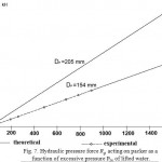 |
Figure 7: Hydraulic pressure force Rg acting on packer as a function of excessive pressure Рlw of lifted water.
|
The study demonstrated that the force of hydraulic pressure Rg, acting on the packer, increases linearly with increase in excessive pressure of lifted water at packer output P∏ (increase in water lifting height Н) and with increase in packer working diameter Dnp. Thus, upon increase of P∏ from 0 to 1500 kpa: at Dnp= 154 mm Rg increases from 0 to 27.8 kN, and at Dnp = 205 mm Rg increases from 0 to 49.8 kN.
In order to verify the reliability of theoretical assumptions Rg = f(PΠ), Eq. (4), the curve in fig.7 shows experimental and theoretical dependences for packer with working diameter Dnp=154 mm where upon experimental variation of PΠfrom 196 kPa to 878 kPa and theoretical variation of PΠT =199.3…877.9 kPa the the force of hydraulic pressure varied in the following range: in terms of experimental data — Rgэ = 3.54 kN…16.24 kN, in terms of theoretical data — Rgт = 3.71 KN…16.35. The divergence between experimental and theoretical data was (4.6…0.7) %, thus confirming the reliability of the equation according to definition of Rgт [6, 7].
Shimming forces Тз and normal pressure ТΝ, acting on packer fixing stop, as a function of hydrodynamic pressure Rg are illustrated in Fig. 8 at constant vertical angle of slope of fixing stops β = 1.326 rad (76о) and internal well diameter Dск = 154 mm.
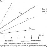 |
Figure 8: Shimming forces Тs and normal pressure ТΝ, acting on packer fixing stop as a function of hydrodynamic pressure Rg . |
The functions Тз, ТΝ = f(Rg) are given without accounting for (Тз, ТΝ) and with accounting for friction forces (ТЗт, ТΝт) of sealing rings of packer body against internal well wall – bottom one upon dynamic mode and top one upon static mode of operation [2 ,7 ].
It can be seen in the figure that with increase in the force of hydraulic pressure Rg on packer fixing stop the active forces Тз and ТΝ also increase. Thus, with increase in from 0 to 5.4 kN ТЗт increases from 0.422 kN to 5.9 kN and ТΝ from 1.7 kN to 23,.6 kN.
In order to verify the reliability of equations for determination of shimming forces Тз, Eq. (5), and normal pressure ТΝ, Eq. (6 ), the plot in Fig. 9 shows theoretical and experimental dependences ТЗт, ТΝт = f(Rg) at β = 1.326 rad (76о) and Dск = 154 mm. Upon experimental variation of Rgэ from 0 to 5.41 kN and theoretical variation of Rgт=0 to 5.45 kN the forces Тз and ТΝ varied in the following ranges: in terms of experimental data — ТЗэ = 0.42…2.16 kN and ТΝэ = 1.7…8.85 kN, in terms of theoretical data — ТЗт = 0.422…2.18 kN and ТΝт = 1.69…8.736 kN. The divergence between experimental and theoretical data was up to 4.9 % for ТΝ and up to 1 % to ТЗ, thus confirming the reliability of the obtained equations.
Upon static mode of hydraulic packer (inactive pump) Figs. 9 and 10 illustrate normal pressure ТΝ and shimming force Тз of packer fixing stop as a function of water lifting height Н at upper limit of optimum vertical angle of slope of fixing stops β = 1.466 rad (84о) and two typical packer working diameters Dпр = 154 mm and 205 mm, respectively [ 2, 7].
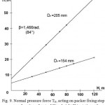 |
Figure 9: Normal pressure force ТΝ, acting on packer fixing stop as a function of water lifting height Н in static mode.
|
It can be seen in the figure that with increase in the water lifting height Н the forces ТΝ and Тз, acting on packer fixing stop increase according to curvelinear relation, increasing with increase in the packer working diameter Dпр.
With variation in the water lifting height Н from 0 to 120 mm the forces ТΝ and Тз vary in the following ranges: at Dпр = 154 mm, ТΝ = 4.01…21.79 kN and Тз = 0.422…2.29 kN; at Dпр = 205 mm, ТΝ = 6.84…60.22 kN and Тз = 0.719…6.33 kN.
In order to verify the reliability of fixation, Eq. (9), that is, validity of the condition Тfr = ТΝ ∙ ffr ≥ Тз, when the friction forces of fixing stop against internal wall of well casing should be higher than its shimming forces Тз, Fig. 7 illustrates the dependences Тfr = f(Н). Calculated values of friction forces Тfr at the coefficient of friction ffr = 0.18 (steel against steel) with increase in water lifting height Н from 0 to 120 m increase and equal to: at packer working diameter Dпр = 154 mm, Тfr = 0.72…3.92 kN >Тз = 0.422…2.29 kN; at Dпр = 205 mm, Тfr = 1.23…10.82 kN >Тз = 0.719…6.33 kN, thus confirming validity of the aforementioned condition with the marginal coefficient of friction forces Тfr in excess of shimming forces, equaling to 1.71.
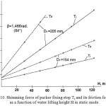 |
Figure 10: Shimming force of packer fixing stop Тз and its friction force Тfr as a function of water lifting height Н in static mode.
|
Aiming at increase in the fixation reliability of packer with pump in well the contacting surface of fixing stops against well wall was made with grooves, when the coefficient of friction increases from 0.15…0.18 to 0.4…0.5 and, respectively, the marginal coefficient of friction force increases to 3.8…4.7. The study established that the reasonable vertical angle of slope β of fixing stop is 1.396…1.466 rad (80о-84о) at the coefficient of friction of fixing stop against well casing ffr = 0.15…0.18 (steel against steel).
With increase in the coefficient of friction to ffr = 0.4…0.5 due to grooved surface of fixing stop, which was in fact implemented in experiments, the lower limit of slope angle of fixing stop can be decreased to 76о (1.226 rad), at which the marginal coefficient of friction forces remains nearly the same at upper limit of the angle (β = 84о) and ffr = 0.18 and equals to 1.60…2.0 [2,7].
Investigation into compression of hydraulic packer
Excessive pressure of lifted water in packer Рп. was selected as the main estimation criterion of compression parameters.
Compression of hydraulic packer against well casing wall by means of hydraulic expansion of sealing ring, bottom one upon dynamic mode and top one upon static mode, was experimentally studied using oscillograms of pressure gauges.
The study revealed that the sealing ring expands in 2.5…3 s after pump start at excessive pressure РПmin = 107.9 kPa and is in steady mode in 1…1.5 s, that is, total time from pump start to steady mode of packer operation equals to 3…4 s. Herewith, the initial pressure of compression does not depend on the water lifting height, and only on elastic properties of the material (rubber) of sealing ring [2, 6].
Tension force Тр of bottom sealing ring as a function of excessive pressure of lifted water Рп in packer upon dynamic mode of its operation is illustrated in Fig. 11 for various packer working diameters Dпр = 154 mm and 205 mm. it can be seen in the figure that Тр increases with Рп according to linear relationship and increases with Dпр. With increase in Рп from 298 kPa to 887 kPa the force Тр varies in the following ranges: at Dпр = 154 mm Тр = 6.58…19.35 kN; at Dпр = 205 mm Тр = 9.0…26.5 kN.
In order to verify reliability of theoretical Eqs. (7) and (8) according to definition of Тр = f(Рп) and Рп = f(Н) Fig. 10 illustrates their theoretical and experimental dependences for packer with working diameter Dпр = 154 mm. In terms of experimental data at РПэ = 298.2…886.8 kPa, ТРэ = 6.5…19.35 kN, in terms of theoretical data РПт = 301.4…887 kPa, ТРт = 6.58…19.35 kN.
At water lifting height Н = 20…89.5 m the excessive pressure of lifted water in packer varies as follows: in terms of theoretical data РПт = 301.4…887 kPa, in terms of experimental data РПэ = 298.2…886.6 kPa.
The divergence between experimental and theoretical data in terms of Тр is up to 1.1 %, in terms of Рп up to 1.06%, which confirms the validity of the equations according to definition of Тр = f(Рп) и Рп = f(Н).
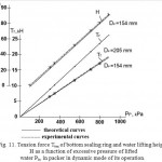 |
Figure 11: Tension force Тten of bottom sealing ring and water lifting height Н as a function of excessive pressure of lifted water Рlw in packer in dynamic mode of its operation.
|
For static mode of operation the compression of packer Fig. 12 illustrates tension forces Тр of top sealing ring as a function of water lifting height Н.
It follows from the figure that Тр with increase in Н increases as well as with increase in packer working diameter аDпр.
Thus, at Н = 30…120 m Тр equals to: at Dпр = 154 mm Тр = 4.35…25.68 kN; at Dпр = 205 mm Тр = 5.85…35.10 kN. Herewith, for Dп = 154 mm ТРэк = 4.15…20.65 kN. The divergence between experimental data at Dп = 154 mm with theoretical data is not higher than 4.6 %, thus confirming the validity of equation according to definition of Тр in static mode of packer operation.
It has been established experimentally that the condition at initial compression Тр ≥ Тretr. (tension force of sealing ring should be higher or equal to retraction force due to its elastic properties) is satisfied. Thus, according to experimental data Тр= 2.33 kN ﺤТretr. = 2.21 kN.
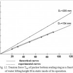 |
Figure 12: Tension force Тten of packer bottom sealing ring as a function of water lifting height Н in static mode of its operation.
|
Investigation into shimming of packer detwisting mechanism
Experimental study was restricted mainly by verification of compliance with the main condition: Eq. (10) of operation of packer detwisting mechanism (cumulative force of lateral friction of pressing rollers should be higher or equal to the twisting force of packer with pump after reactive torque of pump motor upon its start) and definition of rolling friction coefficient and rolling of rubber-coated roller of detwisting mechanism along internal surface of well casing [2, 7].
According to the experiments the main condition of operation of packer detwisting mechanism is satisfied: T’TP∋= 289Н…299Н > = МR/DСК = 179Н…172Н for internal well diameter DСК = 154 mm with marginal coefficient of 1.61…1.73; 173.2Н…200Н > = МR/DСК = 84.5Н…97.5Н for internal well diameter DСК = 205 mm with marginal coefficient of 2.04…2.05.
The rolling friction coefficient of rubber-coated roller along internal steel casing according to experimental data was fк = (0.000175…0.00021), and the coefficient of rolling friction with accounting for the roller diameter was fпер = 0.010…0.012. The coefficient of sliding friction of rubber-coated roller at its lateral displacement along steel casing upon pump start was fтр = 0.78…0.80, that is, complied with the known coefficients of rubber sliding against steel fтр = 0.8.
Investigation into pinching forces and lifting of packer with pump
Experimental results confirmed that upon relief of excessive pressure of lifter water in packer and above packer due to elastic properties of the material (rubber) the sealing rings are retracted to initial position and do not hinder disassembling of packer with pump, that is, there are no friction forces between sealing rings and internal surface of well casing during assembling and disassembling.
The force of packer pinching (detachment of relief valve) according to experimental data corresponds to calculations by Eq. (11) according to definition of TOTP∋ , the divergence does not exceed 4 %. Thus, at Н = 110 m according to experimental data TOTP∋ = 0.56 kN, according to calculations TOTPT = 0,54 kN, the divergence is 3.7 %.
It has been experimentally established that the force required for disassembling (lifting) of packer with pump from well is composed mainly of the weight of pump, packer, electric cable and disassembling rope, the force of rolling of rubber-coated rollers against well casing is negligible (2.5Н…8Н).
According to experimental data the force, required for disassembling of packer with electrical submersible pump ETsV6-10-80 from bench well with the diameter of 154 mm , without accounting for the weight of cable and rope, was 1.30 kN, according to theoretical data, Eq. (12) данным: 1ю27 kN, the divergence is 2.4 %
[2,7 ]
Investigation into verification and adjustment of main parameters of hydraulic packer
The main parameters of hydraulic packer of two typical sizes were experimentally verified and adjusted, they mainly corresponded to their substantiated values: do= 50mm, ζπ= 5.6, S= 15 mm, bk = 50 mm, hK= 15 mm, δK = 7.5 mm, P∏min = 107.9 kPa, β= 760- 840, α 130 – 190 D∏p = 154 mm and 205 mm.
The substantiated and adjusted parameters were applied for development of two typical sizes of hydraulic packers [7].
Therefore, on the basis of the performed experiments of two typical sizes of hydraulic packers UPG-168М and UPG-219М intended for pipeless water lifting in combination with electrical submersible pump ETsV 6-10-80 the involved processes were studied: fixation and compression of packer in well, of pinching detwisting device of hydraulic packer, the main parameters of the considered hydraulic packer were determined, the reliability of theoretical assumptions was experimentally verified with regard to each involved process, their parameters were adjusted with subsequent possibility of application for development of the required typical sizes of innovative hydraulic packers upon improvement of pipeless water lifting tewchnology.
Discussions
As a consequence of the performed experiments with two typical sizes of hydraulic packers UPG-168М and UPG-219М with ejector applied for pipeless water lifting in combination with electrical submersible pump ETsV 6-10-80 the involved processes have been studied: fixation and compression of packer in well, pinching of detwisting device of hydraulic packer, and main process variables have been established.
Upon fixation of packer in well, during variation of pressure in packer Pπ from from 0 to 1500 kPa (dynamic mode): at the packer diameter Dпр = 154 mm the force of hydrodynamic pressure Rg, acting on packer, varied from 0 to 27.8 kN, and shimming forces Тз and normal pressure ТΝ, acting on packer fixing stop, ТЗ = 0.42…5.9 kN and ТΝ = 1.7…23.6 kN; at packer diameter Dпр = 205 mm the force Rg varied from 0 to 49.8 kN, and ТЗ = 0.7…6.3 kN and ТΝ = 6.8…60.2 kN. In static mode of packer fixation in well during variation of water lifting height Н from 0 to 120 m (water column above packer): at packer diameter Dпр = 154 mm the shimming forces Тз and normal pressure ТΝ, acting on packer fixing stop, ТЗ = 0.42…2.29 kN and ТΝ = 4.01…21.79 kN; at packer diameter Dпр = 205 mm ТЗ = 0.72…6.33 kN and ТΝ = 6.84…60.22 kN. It has been experimentally established that the reasonable vertical angle of slope β of fixing stop is 1.396…1.466 rad (80о-84о) at the friction coefficient of fixing stop along well casing fтр = 0.15…0.18 (steel against steel). Aiming at increase in fixation reliability of packer with pump in well the portion of fixing stops contacting with well wall is made with grooves, hence, the friction coefficient increases to 0.4…0.5, and, respectively, the marginal coefficient of friction forces increases to 3.8…4.7 or the angle β decreases to 760.
Compression of hydraulic packer against well casing well by hydraulic expansion of sealing ring (bottom one in dynamic mode, and top one in static mode) has been studied; it has been established that the sealing ring expands in 2.5…3 s after pump start at excessive pressure РПmin = 107.9 kPa and is in steady mode in 1…1.5 s, that is, total time from pump start to steady mode of packer operation equals to 3…4 s. Herewith, the initial pressure of compression does not depend on the water lifting height, and only on elastic properties of the material (rubber) of sealing ring. In dynamic mode of compression (operation of bottom sealing ring) upon establishment of excessive water pressure in packer Рп from 298 kPa to 887 kPa the tension force of sealing ring Тр varies in the following ranges: at the packer diameter Dпр = 154 mm Тр = 6.58…19.35 kN; at Dпр = 205 mm Тр = 9.0…26.5 kN. In static mode of compression (operation of top sealing ring) upon establishment of water lifting height Н = 30…120 m Тр equals to: at Dпр = 154 mm Тр = 4.35…25.68 kN; at Dпр = 205 mm Тр = 5.85…35.10 kN. It has been experimentally established that the condition at initial compression Тр ≥ Тretr. (the tension force of sealing ring should be higher or equal to retraction force due to its elastic properties) is satisfied. Thus, according to experimental data Тр= 2.33 kN ﺤТretr. = 2.21 kN.
Pinching of packer detwisting mechanism has been studied; the compliance of the main condition of operation of packer detwisting mechanism has been experimentally confirmed: T’TP > TR (cumulative force of lateral friction of pressing rollers should be higher or equal to twisting force of packer with pump due to reactive torque of pump motor at its start): for internal well diameter DСК=154 mm T’TP∋ = 289Н…299Н > T’R∋ =МR/DСК=179Н…172Н with the marginal coefficient of 1.61…1.73; for internal well diameter DСК=205 mm T’TP∋ =173,2Н…200Н> T’R∋= МR/DСК=84.5Н…97.5Н with the marginal coefficient of 2.04…2.05. We experimentally determined the coefficient of rolling friction fк=0.000175…0.00021; of rolling of rubber-coated roller fпер=0.010…0.012 and sliding friction of rubber-coated roller at its lateral displacement along steel pipe upon pump start fтр=0.78…0.80, which corresponded to the know coefficients for rubber against steel.
Reliability of the proposed theoretical assumptions has been verified with regard to each running process. The packer fixation in well: the divergence between theoretical and experimental data was not higher than: for – Eq. (4) to 4.6…0.7 % at Rgт = 3.71 kN…16.35 kN and Rgэ = 3.54 kN…16.24 kN; for Тз–Eq. (5) up to 1 % at ТЗт = 0.422…2.18 kN and ТЗэ = 0.42…2.16 kN; for ТΝ – Eq. ( 6 ) up to 4.9 % at ТΝт = 1.69…8.736 kN and ТΝэ = 1.7…8.85 kN, that is, the reliability of the proposed theoretical equations was confirmed.
With regard to compression of packer in well: the divergence between theoretical and experimental data was not higher than: for Тр = f(Рп) – Eq. (7) in dynamic mode up to 1.1 % at ТРт = 6.58…19.35 kN and ТРэ = 6.5…19.35 kN; for РП = f(Н) – Eq. (8) up to 1.06 % at РПт = 301.4…887 kPa and РПэ = 298.2…886.6 kPa; for Тр = f(Н) – Eq. (9) in static mode up to 4.6 % at Тр = 4.35…25.68 kN and ТРэк = 4.15…20.65 kN, that is, the reliability of the proposed theoretical equations was confirmed.
According to definition of forces for pinching and lifting of packer with pump: the divergence between theoretical and experimental data was not higher than: for pinching force of packer (detachment of relief valve) Тотр =f(Н) – Eq. (11) up to 3.7 % at kN and kN; for the force of lifting of packer with pump ETsV 6-10-80 without accounting for the weight of cable and rope ТТР – Eq. (12) up to 2.4 % at Ттрт =1.30 kN and Ттрэ = 1.27 kN, that is, the reliability of the proposed theoretical equations was confirmed.
Main parameters of hydraulic packer of two typical sizes were experimentally verified and adjusted, they mainly corresponded to their substantiated values: internal diameter of packer through hole d0 = 50 mm; coefficient of local losses in packer ζп = 5.6; stroke of back-pressure valve in packer S = 15 mm; the sealing ring dimensions: width bк = 50 mm, sealing portion height hк = 15 mm, sealing wall thickness δк = 7.5 mm; minimum excessive pressure for sealing ring operation = 107.9 kPa; vertical angle of slope of fixing stops β = 76 о -84 о; horizontal angle of slope of rods with rollers of detwisting mechanism α =13о-19о; external packer diameters in operation position of the stipulated typical sizes: Dпр = 154 mm and 205 mm .
The innovative character of packer for electrical submersible pump was confirmed by decision to issue the KZ patent [30].
Conclusions
- On the basis of the performed experiments of two typical sizes of hydraulic packers UPG-168М and UPG-219М with ejector based in pipeless water lifting in combination with electrical submersible pump ETsV 6-10-80, the involved processes have been studied: fixation and compressing of packer in well, pinching of detwisting device of hydraulic packer, and major technological and technical parameters have been determined.
- The performed experimental study of dynamic processes running in the proposed new type of hydraulic packer with ejector based on pipeless water lifting from wells by means of electrical submersible pump has confirmed reliability of the assumed theoretical backgrounds applied upon development of required typical sizes upon improvement of pipeless water lifting.
- The following issues have been experimentally determined: coefficient of packer local resistances ζp = 5.5…5.6, coefficient of friction of rubber-coated roller along steel pipe ffr=0.8, excessive minimum pressure of lifted water required for expansion of sealing ring – 107.9 kPa, force for packer shimming – not higher than 0.75 kN. Major parameters of hydraulic packers of two typical sizes have been experimentally verified and adjusted, which mainly correspond to their substantiated values.
- Application of an innovative type of hydraulic packer with ejector makes it possible to improve main process variables of pump facility: flow rate QPF and efficiency ηPF by 1.2 times at steady technological process and satisfied specifications.
- The experimental results can be recommended for practical application.
References
- A. A. Yakovlev and A. R. Konyrbaev. Study into water lifting from wells upon combined operation of electrical submersible pump and hydraulic packer. Vestn. S-kh. Nauki Kaz., No. 5, Almaty, Kazakhstan, 1998, pp. 108–115.
- A. B. Konyrbaev. Substantiation of parameters and development of hydraulic packers for electrical submersible pumps for pasture wells: Author’s thesis abstract, Cand. techn. sc. – Almaty, Kazakhstan,1999.
- Alan Charles Twort, Don D. Ratnayaka, Malcolm J. Brandt. Water Supply. Butterworth-Heinemann, 2000 – pp: 676
- Gabor Takacs. Electrical Submersible Pumps Manual: Design, Operations, and Maintenance. GulfProfessionalPublishing, 2009. – pp: 440
- M Michael, S. D Khepar, S. K Sondhi. Water Wells and Pumps. McGraw Hill Professional, 2008. – pp: 696
- Phil Hall, Joe Chen. Water Well and Aquifer Test Analysis. Water Resources Publication, 1996. – pp: 412
- A. Yakovlev and A. R. Konyrbaev. Substantiation of parameters of hydraulic packer for electrical submersible pumps aimed for water lifting by well casing. Vestn. S-kh. Nauki Kaz., No. 4, Almaty, Kazakhstan, 1998, pp. 112-122.
- A. A. Yakovlev, E. Sarkynov, B. A. Asanbekov, B. A. Birimkulova. Efficient operation of pipeless underground water lifting in water supply system and melioration. Habarlary, Izv. Akad. Nauk Rep. Kaz., No. 3, 2011, pp. 14-16.
- Z. Zhakupova, A. A. Yakovlev. Improvement of pipeless water lifting in order to increase efficiency of utilization of underground waters. Problems of water apportioning and ways of quality improvement of trans-border rivers of Kazakhstan: Proceedings of International Conference of Bachelors, РhD Doctoral Candidates and Young Researchers. Almaty, Kazakhstan: Kazakh National Academy of Sciences, 2012. pp.150-153.
- Zh. Z. Zhakupova, A. A. Yakovlev, and E. Sarkynov. Theoretical backgrounds for substantiation of pipeless underground water lifting. Study, results: Addendum No. 2.- Almaty, Kazakhstan, 2012, – pp.69-75.
- Zh. Z. Zhakupova. Improvement of pipeless water lifting in order to increase utilization efficiency of underground waters in melioration: Bachelor thesis.-Almaty, Kazakhstan, 2013.
- George E. Totten, ASTM Committee D-2 on Petroleum Products and Lubricants. Tribology of Hydraulic Pump Testing. ASTM International, 1997. P25
- Robert Wayne Bryant Dynamic Analysis of a Hydraulic Pump Valve Ball University of Wisconsin–Madison, 1963 – pp: 164
- George E. Totten, David K. Wills, Dierk G. Feldmann. Hydraulic Failure Analysis: Fluids, Components, and System Effects. ASTM International, 2001 г. – pp: 601
- Mary Ann Borch, Stuart A. Smith, Lucinda N. Noble. Evaluation and Restoration of Water Supply Wells. American Water Works Association, 1993. – pp: 272
- M. Usakovsky. Water supply and water disposal in agriculture. – Moscow, Russia: Kolos, 2002.
- G. Zhelobovsky and M. A. Lavrov. Analysis of operation of pipeless water supply from wells. Improvement of water supply and sewage systems of populated area of Byelorussia: Proceedings, R&D conference. – Minsk, Byelorussia: BelNIINTI,1975. – pp.16-18.
- G. Zhelobovsky, A. D. Gurinovich, and V. D. Gladkov. Device for water supply from wells by means of electrical submersible pumps via well casing. Methods of improvement of operation of water intake facilities and quality of drinking water: Proceedings, R&D conference. – Minsk, Byelorussia: BelNIINTI, 1979. – pp.22-24.
- M. Michael, S. D Khepar, S. K Sondhi. Water Wells and Pumps. McGraw Hill Professional, 2008. – pp: 696
- Phil Hall, Joe Chen. Water Well and Aquifer Test Analysis. Water Resources Publication, 1996. – pp: 412
- G. Zhelobovsky and A. D. Gurinovich. Pipeless suspension of electrical submersible pumps in wells. Gidrotekh. Melior., Moscow, Russia: No. 7. 1981. – pp. 70-72.
- G. Zhelobovsky. Efficiency of water intake and lifting from wells via well casing: Author’s thesis abstract. – Moscow, Russia, 1986.
- S. Ariel’. Experimental devices of pipeless water lifting . Gidrotekh. Melior., Moscow, Russia: No. 2, 1982.
- I. Fabrikov, A. A. Sil’chenko, V. M. Kostyukevich. Device for pipeless water lifting from wells by means of electrical submersible pumps. Agricultural water supply. Express information, Series 3, Issue 2. – Moscow, Russia, 1982.
- A. Skobel’tsyn, A. I. Fabrikov, and A. A. Sil’chenko. Application of electrical submersible pumps for development of wells. Gidrotekh. Melior., Moscow, Russia: No. 2, 1982.
- Report No. 02860047417. KazNIIVKH MMVKH KazSSR. Development of device for pipeless water lifting from wells via well casing of thermoplastic pipes with internal diameter 200 mm and depth up to 150 Dzhambul, Kazakhstan,1986.
- M. M. Trusov, V. N. Fisenko. Hydraulic design of device for pipeless water lifting and its efficiency. Vestn. S-kh. Nauki Kaz. No. 2. – Alma-Ata, Kazakhstan, 1987.
- N. Fisenko. Hydraulic optimization and equipment of water lifting from wells with pipeless installation of electrical submersible pump: Author’s thesis abstract. – Moscow, Russia, 1991.
- Author’s certificate No. 1618844 СССР. Device for pumping of liquid from wells. Yu. P. Kalmykov, A. A. Pevzner, and L. A. Kolodyuk. et al. Moscow, Russia. Published: 01.91.
- Preliminary RK patent No. Packer for electrical submersible pump. A. A. Yakovlev and A. B. Konyrbaev, Astana, Kazakhstan. Application: 26.11.98.
- Report No. 01-42-97 (1.1.016) of State acceptance trials of hydraulic packer UPG-168. – Village Oktyabr: Kazakh MIS, Kazakhstan, 1997.
- A. Yakovlev, and A. B. Konyrbaev. Hydraulic packer for pipeless water lifting from wells. – Almaty, Kazakhstan: Kazgos INTI, 1996.
- A. Yakovlev. Hydraulic packers for pipeless water lifting from wells. Scientific news of Kazakhstan. Express information. Series: Development of modern science. Future of science. Issue 3. Almaty, Kazakhstan: KazgosINTI, 1994.- pp.53-54.
- USSR Author’s certificate No. Hydraulic packer for electrical submersible pump. V. D. Krapivin, Moscow, Russia. Published 22.09.69.
- S. V. Mel’nikov, V. R. Aleshkin, and P. M. Roshchin, et al. Design of experiment in studies of agricultural processes. – 2nd edition, revised and supplemented.- Leningrad, Kolos, Russia, 1980.
- G. V. Vedenin. General procedure of experimental study and processing of experimental data. Moscow, Kolos, Russia, 1967.
- F. S. Zavolishin and M. G. Mantsev. Research methods for mechanization of agricultural operations. – Moscow, Kolos, Russia, 1982.
- Statistical methods of processing of empirical data. – Moscow, Russia, Standards. 1978.
- State standard GOST 24026-80. Research tests. Design of experiment. Terms and definitions. – Moscow, Russia, Standard, 1980.
- Decision on patent issue: Packer for electrical submersible pump, dated 21.11.2014, patent pending No. 2013/1896.1 dated 13.12.2013. A. A. Yakovlev, E. Sarkynov, B. A. Asanbekov, A. T. Tleukulova, Zh. Z. Zhakupova, Astana, Kazakhstan.

This work is licensed under a Creative Commons Attribution 4.0 International License.


