

Manuscript accepted on : 19 August 2016
Published online on: --
Plagiarism Check: Yes
Yousef Jahandideh and Elnaz Pournasiri
Department of Prosthodontics, Dental School, Guilan University of Medical Sciences, Rasht, Iran.
Corresponding Author E-mail: pournasiri_elnaz@yahoo.com
DOI : http://dx.doi.org/10.13005/bbra/2328

ABSTRACT: Despite various impression techniques were done for implant, the quarter of implant position and angle in the mouth is important. So, the aim of the current study was to determine comparison between the new method of impression and connected (contiguous) open-tray method in implants. In this study, 4 DIO implant analogues with the diameter of 3 mm and length of 12 mm were placed perpendicular to the surface of themandibular acrylic model. Times using open-tray technique and four times using acrylic model technique. In the first group (open-tray technique), the impression of copings was connected by duralay (resin pattern GC) and shoulder blade acrylic resin, and casted with the help of a special perforated tray and dental increase Silicon impression materials. In the second group, impression was conducted using acrylic model. In this way, instead of coping impression, DIO system titanium abutments, with a 2 mm cuff, height of 5.5 mm and a diameter of 4 mm, were used. Then the results compared using independent t- tests. Also, two way ANOVA test was also used to show the interaction of positioning and techniques. Results: these results suggest there is no significant difference between the mean absolute deviation of X and Y dimensions using two impression techniques (P>0.05) but a significant difference detected in Z line dimension (P<0.05). These results suggest replacement of open try technique with acrylic method needs more investigations
KEYWORDS: acrylic model technique; open-tray technique; Open-Tray; Implants
Download this article as:| Copy the following to cite this article: Jahandideh Y, Pournasiri E. A Comparison between the New Method of Impression and Connected (Contiguous) Open-Tray Method in Implants. Biotech Res Asia 2016;13(3) |
| Copy the following to cite this URL: Jahandideh Y, Pournasiri E. A Comparison between the New Method of Impression and Connected (Contiguous) Open-Tray Method in Implants. Biotech Res Asia 2016;13(3). Available from: https://www.biotech-asia.org/?p=15922 |
Introduction
Today, implants are an integral part of the prosthetic treatments; and therefore, the success of its prostheses is dependent on several factors including the occlusion, passive fitness of the frames, strict compliance of parts and correct design of components (1). However, what is more important initially is the impression, or the correct transfer of fixtures’ position from the mouth on the cast.
But what makes a difference between impression of implants and natural teeth is the existence of PDL around the teeth resulting in minor tooth movements in all directions. These movements cause impression-induced tiny errors to be compensated; so that they would not affect the treatment. But it is not the same in integrated implants. Due to the lack of movements, even the slightest errors in the exact transfer of the fixture location to the cast can lead to the lack of proper positioning of prosthesis or the fabrication of prosthesis with misfit (2).
Misfit Prosthesis will be followed by the mechanical and biological problems such as loosening of prosthetic screws, screw fracture, and fracture of the implant (3). There are various impression techniques for implants such as splint, pick up, transfer, each of which has its own advantages and disadvantages (4). As far the open-tray or pick up techniques are concerned, when impression materials are removed, the impression coping remains in the mouth. Therefore, the risk of implant angulation errors, or subsequent changes resulting from impression material distortion during impression coping replacement are minimized. Disadvantages of this method include its being time-consuming, the existence of more pieces when removing the impression, the risk of coping rotation during analogue connection, analogue blind connection to the coping, and therefore the risk of misfit (5).
Closed-tray or transfer is one of the other methods of impression. In this way, after removal of impression, coping remains in the mouth and is removed separately. Then it is embedded in the cast after connecting to the analogue. Some of the advantages of this method are its resemblance to the usual methods of impression and the ease of its use. The use of this method on patients having restrictions in opening the mouth or suffering from active gag reflex, as well as on patients with difficult access to the place of opening the screw is helpful (6). However, the main concern in using this method is the risk of deformation of impression material during re-insertion of coping. The probability of this error is more in angled implants (7).
Therefore, a new method was presented in this study. This method not only enjoys the advantage of splinting the parts and thus having no concern about coping impression rotation during the connection of analogue, but also the ease of impression in this method is similar to the closed-tray technique. It is specifically helpful in the cases where there is no access to the place of screw. The aim of this study was to evaluate the accuracy of impression using a new method called acrylic pattern and its comparison with splinted open-tray method. In each group, 4 casts and 4 implants were used. The null hypothesis of this study is that there is no difference between previous rigorous methods and the new method of acrylic pattern.
Materials and methods
This study was a semi-experimental research, in which the observation method was used to collect data. In order to prepare a transparent acrylic cast for the aim of placing the implants’ analogues, on pre-fabricated model of mandible-through putting a height of wax- an edentulous ridge was refabricated; and then it underwent flasking (Figures 1, 2).
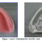 |
Figure 1 and 2: transparent acrylic cast
|
Then 4 DIO implant analogues (usn fa 3012, DIO, Busan, Korea) with the diameter of 3 mm and length of 12 mm, were placed perpendicular to the surface of themandibular acrylic model (Figure 3).
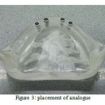 |
Figure 3: placement of analogue
|
The position of analogues was in such a way that, from left to right, the first implant was placed in the premolar area; the second one at a distance of 7 mm from the first one, and the third one at a distance of 14 mm from the first one; so that the distance between the third and the forth implants was 7 mm. Implants were numbered 3, 4, 5 and 6, respectively from left to right; and the numbers 1 and 2 were related to the reference holes (5).
Then, with the help of a lathe CNC (Tor nos-germany) with an accuracy of 0.001mm, two holes were created on a flat surface at the two ends of the ridge, each with a diameter of 2mm and depth of 4mm in one direction. Also, a perfectly smooth surface was prepared on acrylic model at an angle of 90 degrees relative to the first implant, with the help of CNC device; to enable the measurement computer software to put spatial position of the center of the first implant analogue in the zero position (x, y, z = 0) with the help of this index which is repeated in all casts; and to determine the spatial position of the center of subsequent implants while a hypothetical plate passes through this surface and the first implant (Figure 4).
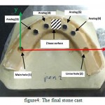 |
Figure 4: The final stone cast
|
Times using open-tray technique and four times using acrylic model technique. In the first group (open-tray technique), the impression of copings was connected by duralay (resin pattern GC) and shoulder blade acrylic resin, and casted with the help of a special perforated tray and dental increase Silicon impression materials (Panasil; Kettenbach GmbH & Co KG) (Figure 5.6)
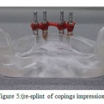 |
Figure 5: (re-splint of copings impression)
|
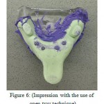 |
Figure 6: (Impression with the use of open-tray technique)
|
In the second group, impression was conducted using acrylic model. In this way, instead of coping impression, DIO system titanium abutments, with a 2 mm cuff, height of 5.5 mm and a diameter of 4 mm, were used. The procedure was that, at first, the laboratory fabricated an acrylic coping with duralay acrylic resin for each of these abutments; and then acrylic patterns were marked in the right direction of placement on the abutment (Figure 7) (5).
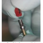 |
Figure 7: (Acrylic pattern marking)
|
After the attachment of the abutment to the analogues on the cast, the acrylic copings were placed on abutments in the right direction and connected by shoulder blades and duralay acrylic resin. After ensuring the completion of polymerization and the possibility of integrated withdrawal of the coping set, impression was performed in the usual way using prefabricated tray and dental increase Silicon impression materials with consistency of heavy body and light body. After the elapse of the setting time of impression material, the cast was removed from the regenerative model of mouth and abutments were also removed from regenerative model and connected to the corresponding analogue (5).
Each abutment and analogue set was embedded inside the respected coping in the right direction, and the cast was poured by stone type IV (Dental stone JV-PADA) and the operation was repeated 4 times.
CMM device (Miracle Nc 685 china) was used to measure the precision of impression in the samples prepared. After ensuring that the device is calibrated, the samples were fixed on a metal plate; and following automatic determination of the probe diameter of the device, the exact position of each implant was determined through the movement of the arm of the device. This kind of positioning was performed on the original model (as a reference) and on the holes of reference, as well as on each of analogues in 3 axes of z, y, x.
For this measurement, the index of device (detector) was placed on the horizontal surface of each cast. Then, the computer part of the device passes a hypothetical plate, as the plate x, through the set of these dots; and the first hole from the right side is assumed on the point zero of 3 axes. Then the detector of this device is located on the center of each analogue, respectively; and its constant number is recorded 3 consecutive times as the spatial position of each implant in x, y, and z dimensions. These intervals were also calculated on the original model (5).
Then, the spatial position of each analogue was determined based on the following formula
![]()
d = spatial position of the points
xᵣ-yᵣ-zᵣ: intervals of the considered points in 4 positions from the point of reference in the original model
xi-yi-zi: the properties of the considered points in 4 positions from the point of reference in the final cast
The mean and standard deviation were used to prepare the final data. The normality of data was examined using one sample k.s test. Then then two techniques of independent t- tests were used to compare data. Two way ANOVA test was also used to show the interaction of positioning and techniques.
Results: The mean absolute deviation from the point of reference in two dimensions of x points from the point of reference, in the four position of placement on the final cast, is given in Figure 4-1 for two impression techniques; where the minimum changes in the x dimension are related to the open-tray technique. Also the related rate is 34 mm in the position of Analogue 3. The maximum changes are related to the acrylic model; and the related rate in the analog 5 was about 0.13 mm. (Figure 1).
Mean absolute deviation in the dimension of y points from the reference point, the minimum changes was related to the open-tray technique in the position of analogue 3 (up to 0.011 mm); and the maximum changes were related to open-tray technique in the analogue 6 up to 0.197 mm (Figure 2).
Mean absolute deviation in the dimension of z showed that minimum changes are observed in the acrylic pattern on analogue 3 up to 0.047 mm; and the maximum changes are related to the open-tray technique in the analogue position 6 up to 0.291 mm (Figure 4-4).
The independent t-test showed that there is no significant statistical difference between the mean absolute deviation of x dimension of the two impression techniques; so that deviation of acrylic pattern technique in the dimension x is greater than deviation in the open-tray technique; but there was no difference between the two techniques in the dimensions y and z. T-test showed that there is a statistically significant difference between the mean spatial position of the points in two techniques of open-tray and acrylic pattern.
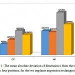 |
Figure 1a: The mean absolute deviation of dimension x from the reference point in four positions, for the two implants impression techniques (OT, AP)
|
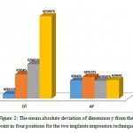 |
Figure 2a: The mean absolute deviation of dimension y from the reference point in four positions for the two implants impression techniques (OT, AP)
|
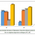 |
Figure 3a: The mean absolute deviation of dimension z from the reference point in four positions for the two implants impression techniques (OT, AP)
|
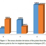 |
Figure 4a: The mean absolute deviation of the points from the reference point in the two implants impression techniques (OT, AP)
|
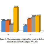 |
Figure 5a: The mean spatial position of the points in the two implants impression techniques (OT, AP)
|
Table 1: Comparison of the mean absolute deviation in different dimensions between the two implants impression techniques (OT, AP)
| OT technique | AP technique | P value | |
| D3 | 0.2061±0.1756 | 0.1096±0.044 | 0.327 |
| D4 | 0.2065±0.1699 | 0.2402±0.2353 | 0.824 |
| D5 | 0.1386±0.0331 | 0.2853±0.2270 | 0.248 |
| D6 | 0.4531±0.2738 | 0.2942±0.2498 | 0.424 |
Table 2: Comparison of the mean spatial position in 4 positions between the two implants impression techniques (OT, AP)
| Mean square | df | Mean Sum | F value | P Value | |
| Implant placement | 0.205 | 1 | 0.068 | 1.783 | 0.177 |
| Technique | 0.003 | 3 | 0.003 | 0.073 | 0.789 |
| Interaction of Implant placement Vs. Technique | 0.112 | 3 | 0.037 | 0.969 | 0.424 |
Discussion
In this experimental study, a new method is provided for the implants impression; the easy application of which is similar to the familiar technique of closed-tray. The difference is that in the closed-tray technique, there is no possibility for splinting the components together; and thus, the possibility of displacement and deformation of the impression material during the placement of coping impression is expected. Therefore, in order to reduce the displacement of impression material, the use of harder materials such as polyether is recommended. But according to studies, deformation in difficult cases such as polyether is more permanent; and increases the risk of inaccuracy (R) (8). In the acrylic model technique, despite its resemblance to the closed-tray technique, there is the possibility of splinting the parts; and thus the parts’ rotation and displacement of impression material can be minimized (9). In this study, CMM device with the precision of 0.001 mm was used for the purpose of examining the accuracy of impression and its comparison.
The results showed that in comparing 2 techniques in y and z dimensions, changes in the connected open-tray is more and it is not significantly different from acrylic model. The only dimension with significant effects of impression on its changes is the dimension; so that the accuracy of open-tray model is greater than acrylic technique. These differences can be due to the placement of analogue above the level of ridge. The result is deeper placement of acrylic copings in the impression material; and thus reduced accuracy of the results. Also in this study, the spatial position of the points (d) was also determined; so that it was recognized that the changes were not significant in the two methods. Various studies have been conducted on the accuracy of impression. Car (10) and Lee et al. (11) compared two methods of open-tray and closed-tray and concluded that the open-tray method is more accurate than the close one. Assip (16) also compared the two techniques of connected and disconnected open-tray and introduced the connected open-tray technique as the best method of impression, regardless of the impression material.
In the present study, in order to evaluate the new method of acrylic model, the connected open-tray method was considered for comparison. The results were not significant and, to some extent, it can be concluded that the acrylic model, despite the convenience, is more accurate than the closed-tray method. In study, compared the verificasign jig with the open-tray method in 3 dimensions of z, y, x. In his study, jig – verificasi had no significant difference with closed-tray method in dimension y which is consistent with the results of the present study. However, in this study, the z dimension had a significant difference with open-tray method. But in this study, the acrylic model had no significant difference with open-tray method in the z dimension. Therefore, the null hypothesis of the research, stating that there is no significant difference between the two methods, is accepted.
Conclusion
Results of this study showed that the impact of acrylic impression method and open-tray on the accuracy of the final cast was identical in z and y dimensions; however, in the x dimension, the acrylic model is more accurate. Therefore, considering the more complex stages of connected open-tray method and its being time-consuming, it may be possible to recommend the use of acrylic model in the cases of high number of implants or in the posterior areas with restrictions in opening the mouth and lack of access to the coping impression.
References
- Peterson LJ، Ellis E، Hupp JR، Tucker MR. Contemporary oral and maxillofacial surgery: Mosby St Louis، Mo; 1998.
- Jorge E، Funkenbusch PD، Ercoli C، Moss ME، Graser GN، Tallents RH. Verification jig for implant-supported prostheses: A comparison of standard impressions with verification jigs made of different materials. The Journal of prosthetic dentistry. 2002;88(3):329-36.
CrossRef - Shillingburg H، Hobo S، Whitsett L، Jacobi R، Brackett S. Fundamentals of fixed prosthodontics. Quintessence، Chicago. 1997:316-7.
- Ness E، Nicholls J، Rubenstein J، Smith D. Accuracy of the acrylic resin pattern for the implant-retained prosthesis. The International journal of prosthodontics. 1991;5(6):542-9.
- Zarb GA، Albrektsson T، Branemark P-I. Tissue-integrated prostheses: osseointegration in clinical dentistry: Quintessence; 1985.
- Hobo S، Ichida E، Garcia L، Hobo S، Ichida E، Garcia L. Complications and maintenance. Osseointegration and Occlusal Rehabilitation Tokyo، Japan: Quintessence Publishing. 1996:239-48.
- Inturregui JA، Aquilino SA، Ryther JS، Lund PS. Evaluation of three impression techniques for osseointegrated oral implants. The Journal of prosthetic dentistry. 1993;69(5):503-9.
CrossRef - Vigolo P، Majzoub Z، Cordioli G. Evaluation of the accuracy of three techniques used for multiple implant abutment impressions. The Journal of prosthetic dentistry. 2003;89(2):186-92.
CrossRef - Misch CE. Contemporary implant dentistry: Elsevier Health Sciences; 2007.
- Carr AB. Comparison of impression techniques for a five-implant mandibular model. The International journal of oral & maxillofacial implants. 1990;6(4):448-55.
- Lee H، So JS، Hochstedler J، Ercoli C. The accuracy of implant impressions: a systematic review. The Journal of prosthetic dentistry. 2008;100(4):285-91.
CrossRef - Assif D، Marshak B، Nissan J. A modified impression technique for implant-supported restoration. The Journal of prosthetic dentistry. 1994;71(6):589-91.
CrossRef

This work is licensed under a Creative Commons Attribution 4.0 International License.


