

Manuscript accepted on : 14 April 2016
Published online on: --
Analysis Workflows Gear Hydraulic Machines
Ildar Ilgizarovich Salakhov*, Ildus Rifovich Mavleev, Vladimir Vladimirovich Voloshko, Ilnur Dinaesovich Galimyanov and Rayaz Khalimovich Takhaviev
Naberezhnochelninsky Institute (branch) Kazan Federal University, Russian Federation, 423812, Naberezhnye Chelny, pr.Syuyumbike, 10A, Corresponding Authors E-mail: iis_kfu@mail.ru
DOI : http://dx.doi.org/10.13005/bbra/2097

ABSTRACT: The analysis workflow in a gear hydraulic machines of different designs. Coefficients of redistribution of moments from unbalanced hydrostatic forces. The dependences of the changes in the coefficients of redistribution of moments from the main parameters of the teeth.
KEYWORDS: gear hydraulic; continuously variable transmission; differential hydra-mechanical variator; mechanical diagram; high-torque differential hydra-mechanical variator
Download this article as:| Copy the following to cite this article: Salakhov. I. I, Mavleev. I. R, Voloshko. V. V, Galimyanov. I. D, Takhaviyev. R. K. Analysis workflows gear hydraulic machines. Biosci Biotech Res Asia 2016;13(2) |
| Copy the following to cite this URL: Salakhov. I. I, Mavleev. I. R, Voloshko. V. V, Galimyanov. I. D, Takhaviyev. R. K. Analysis workflows gear hydraulic machines. Biosci Biotech Res Asia 2016;13(2). Available from: https://www.biotech-asia.org/?p=10952 |
Introduction
Due to the simplicity of the design, gear hydraulic machines are commonplace as non-regulated pumps used to supply non-adjustable pumps applied for small capacity hydraulic transmission with throttle control for lubrication supply and the systems control supply. Geared hydraulic transmission machines are the reversible mechanisms, being the simplest and having the lowest cost of all hydrostatic machines. However, they have failed to find a wide application in the transmission vehicles due to the complexity of continuous variable torque provision at the output shaft and its rotation speed change. The problem of the geared hydraulic machines regulation is solved by their converting into hydro-mechanical differential mechanisms [1].
Forces and torques in gear hydraulic machines
The use of the geared motors and hydraulic pumps as actuating mechanisms in the differential hydrostatic transmissions is based on their following properties [2, 3]:
– Geared hydraulic machines can easily be transformed into a differential mechanism, where the central gear is leading in case of the hydraulic pump, or driven in case of the hydraulic motor; the gears scoring at least two and installed on the axes in a moving body are the satellites;
– The flow rate value on each of the gears varies with the size of the gears and, consequently, with the change of the gear transmission ratio there between;
– The flow rate addition occurs partly due to the forces in the toothed wheel gearing interaction by power transmission from one gear to another, and partly due to overcoming of the resistance moments caused by the action of unbalanced hydrostatic forces of fluid pressure, which create unequal circumferential moments on each of the gears.
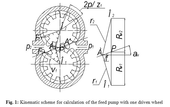
Moments applied to the gears of the gearing hydraulic machine are determined by the effect of the fluid pressure forces to the same areas, which determine the supply process formation. To calculate the supply presented at the Figure 1 the hydraulic pump gears are replaced by flat systems, in which the point A is a gearing point at a given moment of time t. The direct line О1А = ρ1 and О2А = ρ2 connecting this point with the gear center, and the direct О1F1 and О2F2 separate the suction and the injection areas.
By a uniform rotation of the gears, the power imparted to the working fluid:
![]()
where dV – the volume pumped into the pressure line during the time dt; p1, p2 – suction pressure and discharge respectively, MPa; pн – pump pressure, MPa.
This energy is brought to the liquid as moments М1 and М2 supplied from the driving shaft to the gears for overcoming of loads, which occur on the gears due to unbalanced hydrostatic forces. Neglecting the losses, the balance of power on two gears shall be as follows:
![]()
where М1, М2 – moments of resistance on the master and the slave wheels, N·m; ω1, ω2 – angular velocity of rotation of driving and driven wheels; φ1, φ2 – be the angles of rotation of the respective gears.
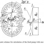 |
Figure 1: Kinematic scheme for calculation of the feed pump with one driven wheel |
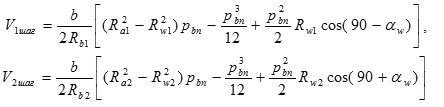
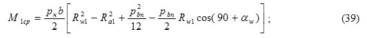
The moments М1 and М2 shall be determined by the following formulas:
![]()
![]()
where b – the width of the gears, м; Ra1, Ra2 – the radii of the circumferences of the tops of the teeth, m.
The mean value of torque on the diving gear is calculated for them, as for other hydraulic machines, by the formula:
![]()
where V0 – the working volume of the hydraulic machine, m3.
Bearing in mind that the pump supply presents a volume change in a time period, we get the following:
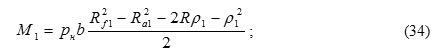
![]()
The distances ρ1 and ρ2 can be determined from Figure 1 by the cosine law.
![]()
![]()
where Rw1 и Rw2 – the radii of the pitch circles of the gears, m; f – the distance from the hooking points to the pole, m; αw – pressure angle, º.
The final formula for determining the pump flow shall be written as follows:
where  coefficient depending only on the geometry of the gears, m2.
Instantaneous torque value on the shaft of the hydro-pump driven by one external gearing wheel can be determined from the energy balance. Having in mind, that on the one part the pump supply flow ,
![]() and on the other part ,
and on the other part ,![]() we shall obtain the following:
we shall obtain the following:
![]()
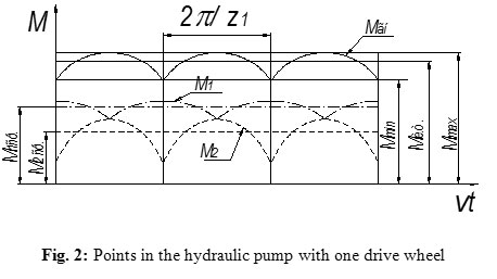
That means, part of the flow rate is taken up directly on the driving gear (on the hydraulic pump shaft), and the other part – on the driven wheel of the hydraulic pump, and is transmitted through the gear ratio from the driven wheel to the hydraulic pump shaft. The moments change schedule from the output rotation angle of the pump shaft is shown in Figure 2.
Taking into the account the formula (9), the expression (10) shall be written as:
One duty cycle of the machine corresponds to the gears rotation to the angular pitch of 2Π/z1 (z1 – a number of teeth of the pinion). The point of teeth contact is moved along the line of engagement. This causes a variability of supply, and consequently – of the torque during the working cycle [4, 5].
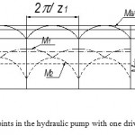 |
Figure 2: Points in the hydraulic pump with one drive wheel |
It is known from the theory of gearing that at turning within the angular pitch the segments ρ1 and ρ2 length varies according to a parabolic law. Geometric values characterizing the gearing enable to express the dependence of the hydraulic machine moment on the gear angle.
The maximum value Мmax is at f = 0:
![]()
The minimum value Мmin at f = pbn/2 (pbn = πmcosαw – the main gearing step).
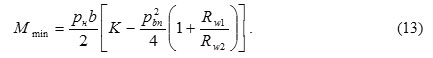
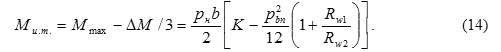
At quadratic law of the moment change, the values Мmax and Мmin enable to determine the mean value of the moment Ми.т.
The average (theoretical) values of the resistance moment М1 and М2 can be expressed in terms of the driving and driven gears supply respectively, at turning to an angle step.
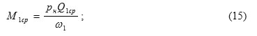
![]()
![]()
![]()
where V1шаг – volume of working liquid delivered by the gear pump leads when you turn on the angular step 2π/z1; V2шаг – volume of the working fluid supplied by the hydraulic pump driven wheel when turning at the angular pitch 2π/z2.


According to the theory of gearing
![]()
where Rb – the radius of the basic circle of the gears, m.
![]()
where m – module gear, m.
For the case, when the engagement length is equal to the unit (ε = 1),
![]()
and taking into account the equation (22), the expressions for the theoretical moments of resistance can finally be written as follows:
![]()
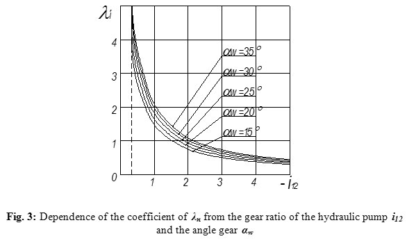
The ratio of the resistance moments in the driving and driven gears can be presented through the coefficient λн, which is defined as

The dependence of the coefficient λн of the hydro-pump with external gear engagement on the gearing parameters are shown in Figure 3.
The conclusion following the formula (25) and the schedule analysis can be that the greatest impact on the coefficient λн is rendered by the transmission ratio of the hydro-pump value and the gearing angle αw. The increase in the number of driven wheels of the pump shall not affect the redistribution of moments [6].
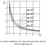 |
Figure 3: Dependence of the coefficient of λн from the gear ratio of the hydraulic pump i12 |
The hydraulic pumps with internal gearing also manifest a redistribution of moment between the driving and driven gears, but the value of the coefficient λн is different; it also depends on either the outer or the inner wheel is driving.
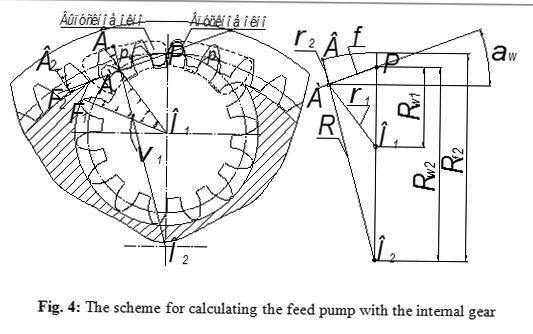
We shall consider the Figure 4 to calculate the resistance moments in hydraulic pumps with an internal driving wheel, where the gears of the hydro-pump are replaced by flat systems, where the point А – is a gearing point at a given moment of time t. Direct lines О1А = ρ1 and ВА = ρ2, as well as the direct lines О1F1 and В2F2 , separate areas of suction and injection [7, 8].
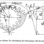 |
Figure 4: The scheme for calculating the feed pump with the internal gear The moments М1 and М2 are determined by the following formulas: |
The moments М1 and М2 are determined by the following formulas:
![]()
![]()
where Rf2 – radii of the circles of teeth cavities crown wheel, m.
Distances ρ1, ρ2 and R can be determined from the Figure 4.
![]()
![]()
![]()
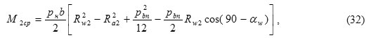
Similarly to the pump with the external engagement gears, the moments М1ср and М2ср are determined through the driving and driven gears supply respectively at turning to an angle step by the formulas:
![]()
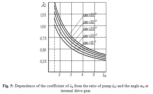
and the coefficien λн:

The coefficient λн of the pump with internal gearing dependence on the parameters of the gearing engagement with an internal driving wheel is shown in Figure 5.
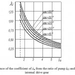 |
Figure 5: Dependence of the coefficient of λн from the ratio of pump i12 and the angle αw at internal drive gear |
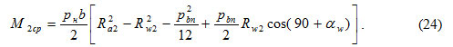
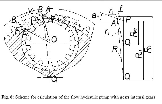
Let us consider the pump with internal gearing and with a drive to the crown wheel (Figure 6). In this case, the values of the moments М1 and М2 are determined by the following formulas:
![]()
where Rf1 – the radii of circles of the tooth of the crown wheel, m.
Distances ρ1, ρ2 and R can be determined from the Figure 5.
![]()
![]()
![]()
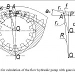 |
Figure 6: Scheme for calculation of the flow hydraulic pump with gears internal gears |
In this case, the moments of resistance are defined as

and the coefficien λн:

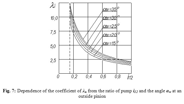
Dependences of the hydro-pump with the internal gearing coefficient λн on the parameters of the gearing with the outer driving wheel are shown in Figure 7.
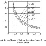 |
Figure 7: Dependence of the coefficient of λн from the ratio of pump i12 and the angle αw at an outside pinion |
Conclusion
The analysis of the forces and moments acting in the gear hydraulic machines enable to make a conclusion that the gear-type hydraulic machines can be converted into the hydro-mechanical differential mechanisms that can be regarded as the first step of hydro-mechanical variators. Hydro-mechanical differential mechanism has the following features: – Two degrees of freedom; – The moments distribution coefficient from the unbalanced hydrostatic pressure forces determines the presence and magnitude of holonomic and non-holonomic constraints between the driving and driven units of hydraulic gear machines; – The use of working fluid flow as a hydraulic connection between hydro-mechanical differential and the one of the possible mechanisms of hydraulic energy converting into mechanical one, which enables to create a continuously variable hydro-mechanical transmission; – Mechanical moment, taken from the carrier of the hydro-mechanical differential mechanism can be added up to another mechanical moment acquired upon the conversion of the hydraulic flow rate; – At changing of the angular velocities of hydro-mechanical differential mechanism units, there occurs a change in hydro-pump supply, which provides an internal automatic performance at converting of hydraulic flow rate into a mechanical one.
This will enable to solve the problem of high-moment hydro-mechanical variators development.
References
- Sharipov V.M. Building and calculation of tractors / Moscow: Publishing Mechanical Engineering, (2004). – 590 p.
- Mavleev, I.R. Development of efficient schemes and designs high-torque hydromechanical CVTs for vehicles: Author. dis. Cand. tehn. Sciences. – Naberezhnye Chelny, (2007). – 19 p. [Мавлеев И.Р. Разработка рациональных схем и конструкций высокомоментных гидромеханических вариаторов для транспортных средств: Автореф. дис. Канд. техн. Наук. – Набережные Челны, (2007). – 19 с.
- Salakhov, I.I. The development of automatic transmissions rational schemes, based on the planetary system of universal multi-threaded differential mechanism: Author. dis. tehn. Sciences. – Izhevsk: M.T.Kalashnikov IzhSTU, (2013). – 23 p. [Салахов И.И. Разработка рациональных схем автоматических коробок передач на основе планетарной системы универсального многопоточного дифференциального механизма: Автореф. дис. Канд. техн. Наук. – Ижевск: ИжГТУ М. Т. Калашников (2013). – 23 с.]
- Patent №2347966 RF IPC F16H 47/04. Differential hydro-mechanical high-torque CVT / Voloshko V.V., & Mavleev I.R. Publ. 27.02.2009, Bull. № 6. [Патент №2347966 РФ, МПК F16H 47/04. Высокомоментный дифференциальный гидромеханический вариатор / Волошко В.В., & Мавлеев И.Р. Опубл. 27.02.2009, бюл. №6.
- Patent №2384773 RF IPC F16H 3/44. Automatic speed planetary gearbox / Voloshko V.V., & Salahov I.I. Publ. 20.03.2010, Bull. № 8. [Патент №2384773 РФ, МПК F16H 3/44. Автоматическая ступенчатая планетарная коробка передач/ Волошко В.В., & Салахов И.И. Опубл. 20.03.2010, бюл. №8.]
- Ildar Ilgizarovich Salakhov*, Vladimir Vladimirovich Voloshko, Ilnur Dinaesovich Galimyanov and Ildus Rifovich Mavleev Universal Differential Mechanism / Biosciences Biotechnology Research Asia, Vol. 11(3), 2014, 1553-1557 pp., https://www.biotech-asia.org/currentissue.php?pg=
- Ildar Ilgizarovich Salakhov*, Ildus Rifovich Mavleev, Ildar Rafisovich Shamsutdinov, Ruslan Ramilevich Basyrov and Voloshko Vladimir Vladimirovich Research and Development of Hydro-Mechanical Differential Variator / Biosciences Biotechnology Research Asia, September 2015., Vol. 12(1), 619-625 pp., http://dx.doi.org/10.13005/bbra/170
- Ildar Ilgizarovich Salakhov*, Ildus Rifovich Mavleev, Eduard Nikolaevich Tsybunov, Ruslan Ramilevich Basyrov and Niyaz Ilgizarovich Salakhov Car Gearbox on the Basis of the Differential Mechanism / Biosciences Biotechnology Research Asia, September 2015., Vol. 12(Spl. Edn. 2), 41-44 pp., https://www.biotech-asia.org/specialedition.php?issue=SE%20SEP%2015

This work is licensed under a Creative Commons Attribution 4.0 International License.


