

Manuscript accepted on : 06 March 2016
Published online on: 06-04-2016
Role of Air Leaks in Causes of Methane Explosions in Coal Mines and Improving Calculation Methods
Valeriy Vitalievich Smirniakov and Victoria Vladimirovna Smirniakova
National Mineral Resources University "Mining University" Russian Federation, 199106, St. Petersburg, 21st line, 2.
DOI : http://dx.doi.org/10.13005/bbra/2019

ABSTRACT: The authors performed the analysis of the circumstances and causes of accidents associated with gas and dust explosions for the last twenty-five years. The conducted research has shown that there is a steady tendency of the stabilization of the number of accidents (associated with impaired stope ventilation) at present time. Most accidents occur at the excavation sites, working off benches of low gradient by the layout systems with flanking pillars and complete roof collapse. As a result of the evaluation of the reasons thereof, conducted by statistical methods and methods of technical analysis, it was found that most excavation sites were provided with the calculated air amount during the accident, while the explosive concentration of methane was observed in the breakage headings and adjacent workings. The main reason for gas normalization violations, according to the authors, is the leakage of supplied air into the collapsed area, the negative role of which lies in the fact that its amount varies continuously in space and time. Currently, all schemes for the ventilation of excavation sites and some coal mines (with gas explosion hazard) are divided into a number of known determinant classification characteristics; the path of air leaks differs respectively. Therefore, the main goal of this research is the development of scientific methods for the calculation of leakage (with the practical use value). This problem is of particular importance during the working of gas seams with the development systems which produce the substantial amounts of worked-out areas. Based on the conducted research, new methods for calculating leaks in the collapse zone were introduced, which allow to determine the air flow amount along the face length on the basis of the minimum input data, and extend the air distribution control capabilities at the excavation site, significantly increasing the safety of mining operations by the gas factor.
KEYWORDS: gas explosions; methane; air leaks; mined-out area; underground accident; causes of explosions; accident analysis
Download this article as:| Copy the following to cite this article: Smirniakov V. V, Smirniakova V. V. Role of Air Leaks in Causes of Methane Explosions in Coal Mines and Improving Calculation Methods. Biosci Biotech Res Asia 2016;13(1) |
| Copy the following to cite this URL: Smirniakov V. V, Smirniakova V. V. Role of Air Leaks in Causes of Methane Explosions in Coal Mines and Improving Calculation Methods. Biosci Biotech Res Asia 2016;13(1). Available from: https://www.biotech-asia.org/?p=7601 |
Introduction
Currently, the intensification of underground coal mining in the modern mining enterprises involves the significant changes in qualitative and quantitative terms of techniques and coal getting technologies. The bulk of the underground coal mining in Russia is provided by the top-slicing systems and the introduction of high-performance mechanized equipment. Technical and economic indicators increase for all the mining production processes in the main production structure – excavation sites. In particular, the lengths, cross-section, the number of ongoing mining and the size of mine field increase; the number of mining sites increases as well. The size of mined-out areas increases accordingly and is characterized by a large volume of cavities in the collapse areas. They represent the paths of leakage or, on the contrary, the air intake, making it difficult to control the ventilation processes, affect the resistance of the ventilation systems.
At that an excavation site during the mineral extraction process remains the place of high concentration of a number of dangerous and harmful factors at the stage of preparation and the second working, the main of which is the possibility of methane explosion. This is explained by the fact that as for the stoop system, the mined-out space plays the major role in the gas situation in the working areas; its share in the gas balance in some cases exceeds 90% (Myasnikov et al., 1987). Mine sections, developed with the top-slicing systems, still pose a serious threat in terms of gas-oil ratio (Puchkov, 1993; Puchkov and Kaledina, 1995). The resulting vast developed spaces, which are the reservoirs of flammable gases, have an aerodynamic connection with the current workings, contributing to an increased flow of combustible gas concentrations in the working areas of excavation sites. This results in a number of explosions and fires of steam-and-gas mixture in coal mines, leading to death of people.
Most of the coal mines in Russia with the work in progress are gas-bearing (Plotnikov, 1992). Over 86% of coal mines are dangerous by the explosion of gas and coal dust, including more than 50% of coal mines, which are overcategorical in methane and prone to sudden outbursts (Paleev et al., 2011). In such circumstances, the issues of ensuring the mine safety are of particular importance during the filling of the workings atmosphere with the combustible gases and forming explosive concentrations in the working areas.
The mined-out spaces as the paths of air movement – air leaks and intakes – are the most difficult to study and calculate as a part of mine ventilation networks, where their role must be properly taken into account in order to effectively control the ventilation process.
The specificity of air leaks is that their amount continuously varies in space and time, which is associated with the development of the mining operations volume, working of new sites and filling cavities, installation of new and destruction of the old ventilation sets, which requires the constant monitoring of the ventilation process in underground structures and leads to air overspending.
Therefore, the main problem of aerodynamics in the mined-out areas is the need to develop scientific methods for the calculation of the air flow in the caved area – leaks. These methods should be practical, allow to obtain reliable results, without the need of a large amount of raw data. This problem is of particular importance during the development of gas-bearing coal seams with the use of caving method.
At present, despite the large amount of research conducted by numerous scientists, the problem of leakage in the caved areas is not fully resolved, due to the variety of factors influencing their dynamics and complexity of processes in the caved areas and the specific conditions of coal mines. The development of effective estimation and leakage calculation methods is a complex multi-attribute task, aimed at improving the safety of mining operations; some aspects of its solving are listed in this paper.
Methodology
A comprehensive detailed analysis of statistical and technical methods, as well as field observations and analysis were carried out to obtain the reliable results in the investigation of leaks as the causes of accidents, allowing to develop specific measures aimed at improving the safety of mining operations on the gas factor.
Statistical and technical research
The estimation of the role of leaks in terms of impact on operation safety in terms of gas and dust factors was based on a comprehensive analysis of all the causes, circumstances, conditions of occurrence and development of accidents, allowing to identify a diagram of an accident with the extraction of elements, which can be controlled by the security means and methods, applied at modern mining enterprises (Tarazanov, 2001-2014; Federal State Statistics Service of the Russian Federation, 2013). In particular, during the emergency analysis in the assessment of the calculation correctness and compilation of gas ventilation balance of the working areas, the air leak amount is determined, taking into account all the leaks in workings both at the design stage and during the exploitation period immediately prior the accident.
The research technique consists of the following studies.
1) Defining of the common characteristics causing the accidents in mines, provided in the investigation materials, which led to explosion.
2) Reasons causing the violation of the openings ventilation, presented in the list form.
3) Systematization of all the causes that led to accidents, conducted by a technical analysis method, and the expertise of the cluster division by key factors peculiar for the mining production – natural, technical, organizational (Ludzish and Kulakov, 1999).
4) A statistical method was used for the quantitative evaluation of the role of leaks in the emergency situation related to gas explosions; its main purpose is to obtain data on the distribution of frequencies and probabilities of accidents on separate groups (clusters) in the space of mine and time (Medvedev, 2009).
Field observations
In order to define the dependence of leakage distribution on the amount of air incoming into the face, and the length of working face, we carried out an experimental research of top-slicing systems in coal and shale mines, as well as potash mines at various ventilation schemes. Observations were performed over a wide variation range of air amount, incoming into the face.
Manufacturing research in the mining areas was carried out in order to define the nature of the air distribution along the face length during the shift. The research included an aerial survey of the area using standard methods, and individual air measurements in the places of possible violations of the air stream structure (face junction, combine working area, movable roof supports). The main goal of these measurements was to evaluate the dynamics of the air leaks in the mined-out space and air inflow in the opposite direction along the length of the face. The measurement of the average velocity of the air was taken by the anemometer with bypass method or the spot measurement in separate sections of the bottom hole face space. The actual areas of cross-sectional sections were determined in the places of air velocity measurements.
When calculating leakages over the caved area, in addition to their absolute values, several parameters were defined, that allowed to perform a more complete assessment of air distribution in the area. These parameters, depending on the ventilation circuit, are shown in Table 1. According to these data and existing regulations, only a total amount of leakage can be defined when calculating the amount of air supplied to the area. Under the production conditions, the amount of leakage along the face length and the airway in air connections, as well as a full length of leaks release, were determined at the air-depression surveys.
The amount of air in the face and the corresponding leak values, as well as the width and the area of ventilated area in worked-out space, were determined by computational methods and well-known formulas.
Table 1 :Design parameters of leaks
| Characteristic parameters, dimension | ventilation scheme | ||
| Direct- flow | Reverse-flow | Combined | |
| Total amount of leaks in m3/min (%) | + | + | + |
| Amount of leaks along the face length, m3/min (%) | + | + | + |
| Amount of leaks along the length of air connections, m3/min (%) | + | – | – |
| Amount of leaks along the length of airway, m3/min (%) | – | – | + |
| Width and area of ventilated zone in mined-out space, m; m2 | + | + | + |
| Distance of full leak output to airway, m | + | – | – |
Analytical studies
To solve the problem of the defining of dependence, the most closely describing the leaks distribution, we chose the least squares method, since each of the features (values of parabolic function qlk (x) and the results of production measurements) has a numerical expression, there are no open variants. The series of paired matched features denoted by “y” – the values of the parabolic function qlk (x) and “x” – are the results of production measurements of qlk. av.
Calculations are performed in the following sequence:
1) Average values of My in the series (“y” version), and Mx in the series (“x” version) are determined by the formulas:
![]()
2) The deviation (dy and dx) of each variant from the value of calculated average number in “y” series and “x” series:
![]()
3) The production of dxdy deviations and their total value Σ dxdy are defined.
4) Both deviations dx and dy are squared, and summed over the “x” series and “y” series.
5) The product (Σ dx2 Σ dy2) is calculated, and the square root is taken from this product.
6) The received values are substituted into the formula for calculation of the correlation coefficient between the characteristics

7) The correlation between these characteristics was estimated on the received values of the correlation ratio.
Results
The statistical analysis of research materials showed that the methane and dust explosions are most likely to occur in the working faces and adjacent workings, and the explosions of metane-dust-air mixture in the workings of excavation sites are the most severe, the most dangerous and have the most complex effects (Smirniakov and Smirniakova, 2015). The comparative results of general statistical and technical methods for analyzing the causes of combustible gases presence in the atmosphere of workings, leading to explosions of gas and dust, are shown in Table 2. It shows that approximately 60% of the total number of causes are directly or indirectly connected to the value of air leak in mined-out face spaces.
Table 2: The results of the technical analysis of the causes gassed air in workings
| Factors | Cause and the source of gas release |
| Natural | Does not depend on the amount of leak
1) Change the mining and geological conditions (mountain range) 2) Intensive release of methane from the loose coal, wall face, working side walls and mined-out space. 3) Sudden coal and gas bursts, pipers (mountain range) 4) Changes in barometric pressure (mined-out space) 5) Roof collapse (mined-out space, mountain range) Depend on the leakage value (including indirect) 6) Thermal drop of ventilation pressure, occurring at breeding fires (mined-out space) |
| Technical | Does not depend on the leakage value
1) Planned fan stop of main and local ventilation (all sources) 2) Restriction of air supply to the mine or on site (all sources) 3) No degassing on mines at ventilation failure means in some mines to keep the methane concentration in the shaft atmosphere within the permissible limits (mined-out space, mountain range) 4) The unsatisfactory condition of main fan and ventilation system (all sources) Depend on the leakage value (including indirect) 5) Breakdown of ventilation mode due to air distribution between workings (all sources) 6) Poor insulation of mined-out spaces, presence of cavings, large air leaks (mined-out spaces, mountain range) 7) Breakdown of ventilation at end cuts (bottom-hole area) 8) Low air velocity in mines (all sources) 9) Use of imperfect drilling in, preparation and working out of benches and development systems (all sources) 10) Thermal drop of ventilation pressure, occurring at breeding fires (mined-out space, mountain range) 11) Poor management of the roof (mined-out space, mountain range) |
| Organizational | Depend on leakage values (including indirect)
1) Changes in mining mode and the organization of work in acceleration without the increase of air feed in faces (all sources) 2) Violations during the degassing of openings (all sources) 3) Engineering mistakes in calculations and air measurements (all sources) 4) Incorrect ventilation mode during the breakdown elimination (all sources) 5) Poor ventilation control in mine workings (all sources) |
The results of the research of air distribution in the mining areas are represented graphically as a dependency of the relative change in air amount along the length of the bottomhole face space.
The results of air measurements at the bottomhole face for a reverse-flow scheme, space show that the leakage value on face junction is characterized by a certain initial value of approximately 50-60% of the maximum leakage value. This value depends on the air drag of the face-end support and the position of a combine with respect to the length of the face. In the first third of face, the leakage value increases sharply, and then gradually decreases. The symmetrical nature of the air distribution along the face length and the width of the bottomhole space were not observed in any face. The nature of air distribution along the face length does not depend on its length and differs only in the location of maximum leakage spot. The diagrams show that shorter faces have the maximum leakage within one-third of face, and in longer ones these maximum leakages are biased towards the middle of face (Figure 1).
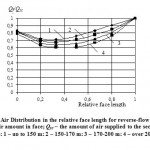 |
Figure 1: Air Distribution in the relative face length for reverse-flow scheme. Qf – air amount in face; Qsc – the amount of air supplied to the section;Faces: 1 – up to 150 m; 2 – 150-170 m; 3 – 170-200 m; 4 – over 200 m |
The leakage value at the direct-flow ventilation on face junction is also characterized by an initial value in the range of 30-40% of the maximum leakage value. The analysis of the results allowed to allocate three zones with various leak intensity along the face length.
The first zone includes 10-15% of the face length, and is characterized by considerable leakage in caved area. The second zone includes the greatest part (80-85% of face length); the leakage nature is close to exponential dependence. The leakage intensity in this area is different and depends on the air resistance of the support unit and actively ventilated area of the mined-out space adjacent to the face. The third zone includes 10% of face length; leaks stabilization was observed in some part of faces, in some cases leakage character remained unchanged, and in others, on the contrary, there was a significant increase in the leakage amount (Figure 2).
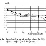 |
Figure 2. Air distribution in the relative length at the direct-flow scheme for different face groups. 1 – Qf.e. / Qa > 1; 2 – Qf.e. / Qa = 1; 3 – Qf.e. / Qa <1 |
According to our opinion, this is due to the influence of the additional air Qa, fed on the belt entry. Considering all these characteristics faces can be divided into three groups, regardless of their length.
It is noted that in case of the increase of the fed air Qa, air leaks change from the curve line, which is characteristic for faces of 1 group to the curve line of face 3 group. These groups can be evaluated quantitatively by the ratio of the air amount at the face end Qf.e to the Qa value. The diagrams show that in case of larger air amount in the bottom section at the face end than that feeding belt entry, air leaks at the face end are more stable than at the smaller amount. A clear quantitative correlation of leaks in face 3 group for similar features was not identified.
The air drag of the air working supporting set also significantly affects the magnitude of the leak. The nature of leakage at that changes as shown in Figure 3, regardless of the length of the face.
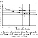 |
Figure 3: Air distribution in the relative length at the direct-flow scheme for the different face groups. 1 – at a significant air drag of lining, which supports air working; 2 – at a low air drag of lining, which supports air working. |
As one can see from the diagrams, faces of 1 group have less air leak increase dynamics along the face length compared to faces of 2 group. A distinctive feature of leaks at faces of this group is the air movement along the space behind the lining, parallel to working face. Faces of 2 group have a relatively small value of the initial leak in junction and the rapid growth along the length of face, at that, the leaks at the junction at the end of face are several times higher than the initial leaks.
In case of the combined ventilation scheme, the air leak value on face junction is within the wide range of 30-60% of the maximum leakage value. The analysis of research results showed three specific positions with varying intensity of leaks along the face length, depending on the position relative to the face front and rear ventilation linkages (Figure 4).
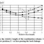 |
Figure 4: Air distribution on the relative length of the combination scheme. 1 – at face passing the front linkage; 2 – at the intermediate position; 3 – at face passing the back linkage |
In the first position, where face passes the front linkage, air leaks were detected along the face length, their behavior was similar to that of the reverse-flow scheme. In the second position, the leak distribution has an intermediate behavior by its nature close to the exponential one. Leakage intensity in this area changes depending on the ratio of air drag at front and rear linkages. In the third position at the face end (approximately 10-15% of the face length) a significant increase of leakages was detected; this is due to a large influence of air drag of back linkage on the air distribution. The observations allow to draw a conclusion that, at a given relative position of the face and ventilation leakages, the amount of leakage in the faces at combined ventilation scheme can be calculated similarly to the direct-flow or reverse-flow schemes depending on face position relative to the face front and rear ventilation leakages.
The analysis of the results of the observations allows to conclude that the distribution of the air flow in different sections along the face length is extremely uneven, due to different resistance of the mined-out space, adjacent to the bottom hole.
It was found that the amount of leakage in the mined-out space at any ventilation scheme can be described by the parabolic curve equation, where its top within the tolerance range corresponds to a maximum leakage value, and the segment between the point of origin of the Cartesian coordinate system and the point of intersection of the parabola right branch with the x-axis is the length of face. In all these cases the value of the correlation ratio is within Ryx = 0.71 – 0.92, it indicates a high enough correlation ratio between these features.
After several translations we got formulas for calculating the leakage along the face length at reverse-flow scheme:

where qj is the air leak in face junction, m3/s;
L – face length, m;
x – distance along the face, where the leakage is calculated, m;
a – coefficient, depending on the face length.
In this formula qj may be defined as the difference between the air amount incoming the site and the air amount at the beginning of face. The formula for leakage calculation along the face length can be applied if qj > 0. If qj = 0, i.e. there are no leaks at the face junction, the parabolic air distribution is symmetrical. The formula to calculate the leakage along face length in this case takes the following form:
![]()
where qlk are the maximum leakages in the middle of face, m3/s.
qlk can be defined according to formula as the difference between the amount of air incoming the site and the air amount in the middle of face.
Formula for the calculation of the leak along the face length for direct-flow scheme:
Formula describing the distribution of air leaks along the face length at combined scheme:
– in case there are no leaks at the front linkage is the same as formula (6);
– in case there are prevailing leaks at the back linkage:

– in case there is a uniform leakage distribution between linkages:
![]()
– in case there are no leaks on the rear linkage:

Nomograms can be constructed to make it easier to use the developed calculation methods in practice, showing the obtained dependences in relative dimensionless quantities with regard to certain ranges of factor changing a and kn for the appropriate ventilation scheme.
Discussion
For calculations in practice, it is necessary to take into account the fluctuations in the air amount in face by multiplying the obtained results by the amount of the calculated correction factor kc, which depends on many complex changes of factors during the second working. The basic parameters are: cross sectional area of the working face; depth of the worked seam; combine position in the face; total air drag of lining in mining complex, dummy insulator (for direct-flow schemes) and collapsed roof rock; combine and conveyor operation; clutter junctions, external factors, etc. (Miletich, 1962). By definition it takes into account fluctuations in non-uniformity in the magnitude of the air amount of metering face points, including the maximum value of leakage. The proposed parabolic dependences for calculation with this factor depend on the location of all the points of a parabola, and consequently determine the nature of the leak. The analytical calculation with acceptable accuracy range of this factor variation based on the impact of the above factors, for example, changing of the aerodynamic qualities of caved ground is problematic since such data may not always be reliably identified and differentiated in the course of production observations. It is much easier to determine this coefficient based on the results of periodic aerial surveys; minimum and maximum air amounts in face and working (where air moves into the face) are measured during these surveys.
In some cases, a clear correlation between the length of the face and the value of the kc coefficient was not detected; this can be explained by the additional effect of mining and technical factors during the observation process, for example, work of machines and mechanisms in face and the surrounding workings. However, in case of the increase of the face length there is a tendency of the increase of the kc coefficient. You can also note that the maximum kc coefficient and the largest spread of values are typical for the direct-flow and combined schemes, and minimum values were observed at reverse-flow schemes.
The a coefficient was defined empirically for different ventilation systems, depending on the face length, the total air drag of supporting ventilation working, set of the mining complex and mined-out space as well as face position relative to ventilation linkages. In case of reverse-flow schemes the maximum leakage spot for shorter faces is within one third of a section from the beginning of the face length, and in the longer ones it is biased towards the middle of face. The coordinates of the point defining the parabola vertex change at that along the abscissa and ordinate axes.
We can get the quantitative characteristics of air leaks in mined-out space and the corresponding air distribution along the length of face with these formulas and nomograms, built according to the proposed method, based on a minimum number of initial data on the initial leakage value in face junction and air amount supplied by coal heading.
Conclusion
Based on the complex statistical and technical analysis of the presented data on the causes and sources of gassed air in workings, leading to explosions, we can conclude the significant influence of leaks in the mined-out spaces on the composition of the atmosphere of breakage heading and its changes.
The results of field observations and analysis showed that the leakage amount in a mined-out space under any ventilation scheme can be described by the parabola equation; its vertex corresponds to the maximum value of leakage, and the segment between the point of origin of the Cartesian coordinate system and the intersection of the right branch of the parabola with x-axis corresponds to face length. In all these cases the value of the correlation ratio indicates a rather high correlation between these features; this allowed to propose the method of leakage calculation by the formulas, based on parabolic dependence.
The main practical advantage of the developed techniques is the ability to get the closest to in-situ (actual) results with the minimum number of available source data. Such input data may be the total air amount supplied by the coal heading, the amount of air at the beginning of face (along the direction of air flow) and the difference between them, the leakage component on face junction. These values are determined by air measurements at the appropriate points, and the resulting figures of a number of factors affecting the dynamics of the leaks in the mined-out space.
Since the basic requirements for operational safety on the gas factor are primarily aimed at providing effective ventilation of mining sites, the timely calculation of leaks promotes accurate estimation of the aerologic situation in the breakage headings and is one of the main measures of its control.
References
- Klishin, V.I., L.V. Zvoryshin, A.V. Lebedev and A.V. Savchenko, 2011. Security Issues and New Technologies of Underground Coal Mining. Novosibirsk: “Novosibirsk Writer” Publishing House.
- Kolesnicheko, E.A., V.B. Artemyev and I.E. Kolesnichenko, 2013. Sudden Methane Outburst: Theoretical Foundations. Moscow: Gornoe Delo, Kimmersky Centre.
- Ludzish, V.S. and G.I. Kulakov, 1999. Accidents and Injuries in Mines of Kuzbass and Harm-Reduction Measures. Novosibirsk: Publishing House of the Russian Academy of Sciences.
- Maslyaev, A.E. and I.N. Lindenau, 1973. Defining Width of Ventilated Area of Mined-out Space under Pillar Mining System. Proceedings of EastSRI, 19: 89-93.
- Miletich, A.F., 1962. Air Leaks in Mines. Moscow: Gosgortekhizdat.
- Medvedev, A.E., 2009. Risk Assessment Methods in Coal Mines. Mining Informational and Analytical Bulletin, 8: 86‑90.
- Myasnikov, A.A., L.S. Ryabchenko and V.A. Sadchikov, 1987. Gas Emission Control at Bank Excavation. Moscow: Nedra.
- Oganesyan, S.A., 2004. Accident in “Mine “Tayzhina” Branch of JSC OUK “Juzhkuzbassugol” – Chronology, Causes, Conclusions. Coal, 6.
- Paleev, D.Y., I.M. Vasenin, V.N. Kosterenko, E.R. Schrager, A.U. Kraynov, O.U. Lukashov and U.F. Rudenko, 2011. Shock Waves at Explosions in Coal Mines. Moscow: Gornoe Delo, Kimmersky Centre.
- Patrushev, M.A. and E.S. Dranitsin, 1974. Airing of Highly Mechanized Faces. Donetsk: Donbass.
- Petrosyan, A.E., 1998. Ways to Prevent Human Casualties in Mines. Occupational Safety in Industry, 7: 44-47.
- Plotnikov, V.M., 1992. Is Rescuers Occupational Safety Ensured at Risk of Gas and Dust Explosion in Coal Mines? Occupational Safety in Industry, 1: 29-33.
- Puchkov, L.A., 1993. Aerodynamics of Underground Mined-Out Spaces. Moscow: Moscow State Mining University.
- Puchkov, L.A. and N.O. Kaledina, 1995. Methane Dynamics in Mined-Out Spaces of Coal Mines. Moscow: Moscow State Mining University.
- Federal State Statistics Service of the Russian Federation, 2013. Statistical Yearbook of Russia. Moscow.
- Ruban, A.D., V.B. Artemyev, V.S. Zaburdyaev, V.N. Zakharov, A.K. Loginov and E.P. Yutyaev, 2011. Preparation and Development of Very Gassy Coal Seams. Moscow: Gornoe Delo, Kimmersky Centre.
- Smirniakov, V.V. and V.V. Smirniakova, 2015. Comprehensive Analysis and Assessment of the Role of Hard-to-Handle Factors in the Reasons of Methane and Coal Dust Explosions in Mines in Russia. Biosciences Biotechnology Research Asia, 12(1): 56-69.
- Tarazanov, I., 2001-2014. Results of the Russian Coal Industry for 2001-2013. Coal.
- Ustinov, A.M. and S.G. Kaliev, 1973. Laws of Air Leaks Distribution in Mined-Out Space of Face under reverse-Flow Ventilation through Pillar. Proceedings of EastSRI, 19: 94-100.
- News bulletin of the Federal Service for Ecological, Technological and Nuclear Supervision, 2006, 4.

This work is licensed under a Creative Commons Attribution 4.0 International License.


