

Manuscript accepted on : 01 March 2016
Published online on: 24-03-2016
Kaipova Zhanar Nurmahanbaevna, Marat Isakovich Satayev, Rustem Feliksovich Altynbekov and Abdilla Abibullaevich Saipov
M. Auezov South Kazakhstan State University, Kazakhstan. Corresponding Author Email: rustik2030@inbox.ru
DOI : http://dx.doi.org/10.13005/bbra/2001

ABSTRACT: The membranous biogas treating research allowed determine optimal parameters of the process, affecting the membrane separation efficiency, permeability and selectivity. The working pressure falls within the limits of 0.6 MPa. Themembranousgastreatingregularitiesinamembraneapparatusweredetermined. The concentration-permeability relation and pressure effect on the permeability were determined. A mass transport mechanism through the membrane pores was established. The membrane structure and material basic requirements and membranous process principle at the gas treating were established. Relation of the membrane mass-transfer coefficient to a permeate flow on the phase rate, the mass-transfer coefficient in the membrane pores on an inside diffusion coefficient showed that increase in the rate results in increase of the mass-transfer coefficient, and also that while the external mass-transfer resistance determines the overall process rate, the process can be intensified.
KEYWORDS: Production; Concentrated; Methane; Biomass
Download this article as:| Copy the following to cite this article: Nurmahanbaevna K. Z, Satayev M. I, Altynbekov R. F, Saipov A. A. Production of A Highly Concentrated Methane by the Membranous Biogas Treating, Formed at the Biomass Densification Based on Agricultural Wastes. Biosci Biotech Res Asia 2016;13(1) |
| Copy the following to cite this URL: Nurmahanbaevna K. Z, Satayev M. I, Altynbekov R. F, Saipov A. A. Production of A Highly Concentrated Methane by the Membranous Biogas Treating, Formed at the Biomass Densification Based on Agricultural Wastes. Biosci Biotech Res Asia 2016;13(1). Available from: https://www.biotech-asia.org/?p=7394 |
Introduction
A rational use of agricultural wastes is a great and important current problem.[1,2]. It is related, on the one hand, to the opportunity to use the vast biomass energy potential to produce a liquid and gas eous fuel (biogas), on the other hand – with the need to prevent contamination of water bodies, soil infection by malignant bacteria and helminths, contained in manurial drains of stock-raising farms. Both these aspects became the object for studies and experiments.
The most commonly encountered method to produce energy from the biomass is an anaerobic (without access of oxygen) fermentation of agricultural wastes [3-5]. Produced in a result of this process products– the biogas and fermented semi fluid mass – are of considerable value as a gaseous fuel and organic fertilizers.
At the first stage of the anaerobic fermentation of organic substances by the biochemical degradation (hydrolysis), there is a decomposition of macromolecular compounds (hydrocarbons, fats, protein substances) to low molecular organic compounds [6-10]. At the second stage, with the participation of acid-forming bacteria, there is the further decomposition with the formation of organic acids and their salts, and alcohols, СО2 and Н2, and then H2S and NH3. The final bacterial change of the organic substances to СО2 and СН4 occurs at the third stage of the process (methane fermentation). Besides, an additional quantity of СН4 and Н2О is formed in the following from СО2 and Н2.These reactions flow simultaneously, at that, the methane-forming bacteria specify to their living conditions considerably higher requirements than the acid-forming bacteria. Thus, for example, they need the absolutely anaerobic environment and more time for the reproduction. The methane-forming bacteria anaerobic fermentation rate and scales depend on their metabolic activity.
Biogas plants meant for a manure and agricultural was tesrecycling are being constructed[11,12]. Besides the plant, including fermentation cabinets,gas holder and the fermented mass (sludge) storage, a pumping unit for the sludge transfer to fields and electric station, the biogas-powered, is being built.
The biogas production interest has considerably increased in recent years. This is shown not only in the increasing number of planned and building biogas plants, but also in the interest of many farmers, public services, enterprises, politicians and private economies [13].
By its properties, the biogas is close to a natural gas [14].
A considerable part of the fuel gas can be produced from alternative sources of raw materials by the anaerobic decomposition of effluents, agricultural wastes, and so on. At that, the biogas preparation (its cleaning from СО2, Н2S and drying with the following compression for the storage and distribution to users) using the membranous methods in comparison with the traditional one, for example with absorption and adsorption, may give a significant economic effect [15].
The biogas, produced by the anaerobic decomposition of wastes, contains methane (≈60%(gen.)) and carbon dioxide (≈40%(gen.)). The gas contains hydrogen sulfide, ammonia, water vapor; its heating value is low – 19.5-19.8 MJ/m3. After the cleaning and drying the gas should contain at least 98%(gen.) of СН4 (with heating value at least 33.0 MJ/m3), Н2S concentration should not exceed (3-5) 10– 4 % (3-5 mln–1). Several variants of the process organization, for each of which we determine the membranes required surface, compression costs, methane extraction degree from the base mixture at different conditions (pressure, decomposition stages number and recycle rate in the schemes with the recycle),are possible. СН4high extraction degree can be achieved using a two-stage scheme, however, at that, the membrane required surface and energy costs increase. The pay back period of the plant by the base gas is less than 3 years, at that, with increase in the cleanable biogas consumption this period reduces. In the decomposition to one stage, methane concentration in the fuel gas reaches 98% (gen.). At increase in the stage number (operation in a cascade mode) an achievement of high – up to 90% – methane recovery degree from the base biogas is possible. It is evident that even at high (3540 m3/h) gas loads, the membranous plant operation is cost-effective.
It is taken to be [16] that the fuel gas considerable part in the nearest future will be produced from alternatives ources of raw materials by the an aerobicde composition of the effluents, agricultural wastes, and soon. At that, the biogas preparation (its cleaning from СО2, Н2S and drying with the following compression for the storage and distribution to users) using the membranous methods in comparison with the traditional one, for example with absorption and adsorption, may give a significant economic effect.
A technical and economic assessment of the fuel gas production using composite membranes MEM-079 was carried out [16, 17]. Several variants of the process organization, for each of which we determined the membranes required surface, compression costs, methane extraction degree from the base mixture at different conditions (pressure, decomposition stages number and recycle rate in the schemes with the recycle), were considered. The following data were taken as a basis of the assessments: the base gas composition –62% (gen.) СН2 38%(gen.) СО2, moisture; required product composition(dried fuel gas) – 98%(gen.) CH2, 2%(gen.) СО2; the base flow pressure– 0,5 MPa; load by the base biogas– 400 m3/h.СН4 high extraction degree can be achieved using the two-stage scheme, however, at that, the membrane required surface and energy costs increase. Analyzing the relationship between the СО2/СН4 achievable decomposition factor and cleaning process parameters in terms of the one-stage scheme, it may be concluded that the decomposition factor considerably influences on the extraction degree only to some defined value (in this case α=10). This is confirmed in terms of other gas membranous decomposition processes. Comparison of different biogas cleaning methods, including the membranous one, is given in reference [16].
In 1985, Monsanto Company put into operation the biogas cleaning industrial plant, produced from municipal effluents with the help of apparatus on hollow fibers “Prizm” [18]. A gas for a separation is fed under 2.0 MPa pressure. In a result of the cleaning, СО2 concentration reduces from 34 to 2% (gen.). A minimal load by the accompanying gas is 300 m3/h.The payback period of the plant is at least 6 years, moreover, with increase in the cleanable biogas consumption this period considerably reduces.
The papers [19, 20] made a comparison of the biogas cleaning costs by means of membranes of GKSS research center and absorption methods – by water washing-out and ethanol a mine (MEA and DEA) cleaning. Computations were carried out for the load by the base gas 118, 1180 and 3540 m3/h; the gas pressure delivered for the cleaning – 1.5 MPa.
The test data of the pilot plant with apparatus of a flat chamber type(MEM 079 membrane) showed that even at the separation into one stage , methane concentration in the fuel gas reaches 98% (gen.).At increase in the stage number (operation in the cascade mode) the achievement of high – up to 90% – methane recovery degree from the base biogas is possible. It is evident that even at high (3540 m3/h) gas loads, the membranous plant operation is cost-effective.
Costs for the membranous cleaning,resulting from the pilot and industrial plants operation were compared with costs for absorptive “Selecsol process” (an absorbent – dimethyl polyethylene glycol ester) [21]. It follows from the obtained data, that the membranous separation method can be effectively used for the biogas cleaning.
A break down of solid domestic waste (SDW), on 55-70% consisting of organic compounds, carries to a large extent identically oafermentation of highly polluted waste waters or municipal sewage treatment residuals [22]. Ina result of this process, the biogas having a combustion heat 18900 – 25100 kJ/m3 (4500 – 6000 kcal/m3) and the following averaged composition:methane – 50-65%, carbon dioxide – 30-45%, hydrogen sulfide – 0.2-0.8%, nitrogen, oxygen, hydrogen – 1-2%, aromatic hydrocarbons, esters – up to 1%, is formed. The biogas average humidity is 35-40%.
By the ballast and hydrogen sulfide cleaning and drying, the biogas combustion heat can be increased up to 27200 – 31400 kJ/m3 (6500 – 7500 kcal/m3), or up to 80% of the natural gas combustion heat. Obtained at the municipal solid waste landfills, the biogas can be used as a fuel material for municipal purposes and agriculture, as well as for electric-power generation. At the same time, the biogas recovery from the land fills allows improve their environmental situation, reduce atmospheric contamination and practically eliminate spontaneous combustion of the wastes.
The paper [23] gives a scheme for production of combustible gases using membranous contactors, integrated with bio reactors. It presents results of microorganism selection to produce the biogas (methanogenic community) and hydrogen from glucose at lactate decomposition. A continuous an aerobic biomass densification in to the biogas by a stable methanogenic community of microorganisms, which is formed during 4 weeks of cultivation, at that the biogas output was 48 ml/l of a liquid culture a day (0.6 m3/kgof a dry biomass), was developed. The average hydrogen capacity is 0.25 mlH2/min of 1 mg protein (0.25 l of H2/ 1 kg raw material). It was shown that the membranous contactors use at the separable gas eous mixture feeding gradually by a counter flow to the adsorbent parallel flow, allows achieve up to 98% of the target component separation efficiency at 7 parallel flows of the liquid carrier (the membrane total area was 280 cm2). The researches were carried out on model mixtures He+CO2 (80+20 gen.%). In combination with the membranous contractors with an asymmetric membrane on the basis of polyvinyltrimethylsilan (a thickness of the selective layer is 0.2 mcm), an effective production of combustible gases of a technical purity is possible (CH4up to 95 gen.%, H2upto 98 gen.%).
The membrane as distinguished from “accumulative” systems for cleaning of gases (active carbon, ion exchange resins, etc.) does not accumulate impurities inside, that excludes a probability of their penetration into the purified gas. The detained particle size is determined by the membrane structure, i.e. by its pore size.
The search of new capabilities of the membranous technologies on both developments of new membranous process to solve actual applied problems and optimization of available processes’ process flow diagrams puts forward the whole complex of problems, related to the development of algorithms and programs on their base. They will allow carry out a preliminary calculation of various processes (or their combination), speed up the output on the optimal parameters, and reduce, by the same token, a period for pre-project working out, by selection of the optimal parameters of the process and scheme basic stages as a whole. This will allow at the selection of definite separation modes increase the membranes’ permeability and selectivity by the target components with achievement of the membranes’ functional characteristics stability.
The biogas membranous cleaning offered technologies will provide the high-effective methane concentration. The intent, basic functions of the membranous apparatus and technologies are based on a mechanism polished by a centuries-old nature evolution. It allows carry out processes of separation, concentration and purification of mixtures on a molecular and supra molecular level with simultaneous utilization of valuable products. The reagent lessness, exclusion of phase changes and use of dissolvent, energy saving, ecological cleanness, comparative simplicity of the technological processing and relatively low temperatures provide the high competitiveness and wide use of the membranous processes at the biogas cleaning.
Material and Methods
Classical and modern physical-chemical research methods, allowing obtain total characteristics of the research objects, by which it is possible to estimate a conformation almolecularstate, properties and availability of different functional groups and properties of materials, were used in the paper. Modern measuring means, metrological standards, methods of statistical analysis of the measuring results, ensuring the measurements’ uniformity and desired precision, identification of admissible errors and faults of the results and limits, which should not be overstepped at the specified probability, were used in the scientific-research work with a view to enhance the biogas safety and quality, reliable accounting of all kinds of material and energy resources, conformity of developments by the technology, reliability of determinations in the researches and scientific developments, control of the working condition safety, environmental protection. The units of measurement correspond to the metrological rules and norms of SI system.
A laboratory-scale biogas plant with its reactor volume in 0.25 m3 was developed and produced for the experimental check and demonstration of the renewable energy resources potentials, as well as for the cattle manure an aerobic fermentation modes processing in the laboratory conditions in M. Auezov SKSU .
According to the scheme, foreign impurities, such as wood chips, straw, stones, coarse long stalked orts, and so on, are removed from the manure. The liquid manure purified from these impurities is supplied into the bioreactor for the anaerobic fermentation.
A microflora that gradually decomposes organics ubstances to volatile fatty acids, which under the action of syntrophic bacteria and methane-forming products change to the gaseous products – methane and carbon dioxide, is developed in the manure during the fermentation. At the same time, at the manurefermentation, its deodorization,worming process, killing of weed seeds’ property to germination, and change of fertilizing substances into a mineral form is provided.
The biogas plant consists of three base apparatus – the bioreactor for the manure anaerobic fermentation, gasholder, apparatus for preparation of the manure to the fermentation, as well as auxiliaries to provide the bioreactor system functioning. The bioreactorisa cylindrical vessel –methane tank from a black steel by 7mm thickness. The methane tank height is 1.5 m, its diameter is 530 mm. The reactor is equipped by an electric heating unit with the heat-exchange surface area in 0.33 m2.
A mixing of a substrate in the reactor is hydraulic with the help of a pump and pipelines with valves. At the pump operation in the mixing mode, the substrate is taken from the reactor by the pipelines in its upper part.
The fermented manure removal occurs as a fresh portion comes in through the pipelines for the effluent removal.
For the reactor discharge, there is a discharge gate in its bottom part. Table 1 presents basic engineering performance of the biogas plant.
Table 1: Basic engineering performance of the biogas plant
| Indicators | Unit of measurement | Value |
| The bioreactor total volume | m3 | 0,25 |
| A gas space volume | m3 | 0,07 |
| Processing temperature at a mesophilic mode – M, at a thermophilic mode – T | оС | 35-37
55-57 |
| Duration of the processing | 24 hours | 20-22 at М
12-15 atТ |
| Power of the pump for the manure mixing | kW | 0,37 |
| Installed capacity of the heating unit | kW | 2,0 |
| The heat-exchange surface area | m2 | 0,33 |
| Productivity:
By the base manure М-Т By the biogas М-Т |
l/day l/day |
10-15 100-170 |
| Pure mass | kg | 450 |
General requirements to the biogas plants, an aerobic conditions in the methane tank, temperature condition compliance, acid-base balance, requirements to characteristics of the convertible wastes, the bioreactor operation mode, requirements to the structure, water and gas impermeability, the methane tank structure reliability, control and measuring instruments, requirements to the biogas gathering facilities, were determined by the following standards: GOST R 52808-2007 Unconventional technologies. Energetics of bio-wastes. Terms and definitions, GOST R 53790-2010 Unconventional technologies. Energetics of bio-wastes. Specifications to the biogas plants, GOST 14920-79DRYGAS. A method for determination ofa fractional analysis, Process procedure. The biogas production from the solid waste landfills. Scientific and technical information office of the municipal economy academy. Moscow 1990,GOST 22387.2-97 Methods for determination of hydrogen sulfide and mercaptan sulfur[24-39].
Results and Discussion
A selection of the working pressure depends on the membranous channel resistance. Obtained experimental values of the permeability dependence on the working pressure show the following characteristic moments (Figure 1). The permeability against the pressure increases in the beginning, but this dependence is nonlinear and then becomes sensibly constant.
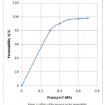 |
Figure 1: Effect of the pressure on the permeability
|
Increase in the pressure results in increase of the membrane surface impurities concentration.
Figure 2 presents the pressure – selectivity relationship. With increase in the pressure, the selectivity decreases, as in the pressure increase, the selectivity increases by all components, i.e. decreases by the required component.
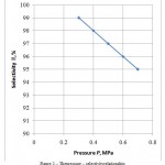 |
Figure 2: The pressure – selectivity relationship
|
Figure 3 presents the rate effect on the permeability, from which it is seen, that with increase in the flow rate the air permeability increases.
A moving force of the process is the pressure difference. The membrane spore sizes or external pressure is selected in such a way that the molecules’ free length should be more than the pore size, i.e. Knudsen flow should be in the pores. At the Knudsen flow, the stream is inversely proportional to the molecular mass mean square. This relation ship determines the separation coefficient.
In large pores, when the pore diameter is larger than the adsorptive molecules’ mean free path, the advantageous transfer is normal or volume diffusion.
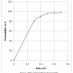 |
Figure 3: Effect of the rateeffecton the permeability
|
The assumption that the diffusion transfer is carried out in a result of sequential periodical bursts of diffusing molecules from one equilibrium position to another forms the basis of a molecular-kinetic consideration of small molecule diffusion (molecules of simple gases) in a polymer. Such transferability is usually related to availability of any free volume in a polymeric environment. i.e. some intermolecular intervals of different form and size, conditioned by both movement of a polymeric matrix segments, and the diffusing molecules’ transfer. These positions were taken as the basis of some theoretical correlations, obtained by researchers, which based on different assumptions and serve to explain experimental results on determination of a viscosity, solubility and diffusion in the polymers. Therefore, dealing with “free volume theory” term, of ten used in qualitative interpretation of experimental results, we should fairly imagine that the question is not about a rigorous mathematical formulation of the process, but about some complex of different theoretical calculations.
However, admittedly the base model of “free volume” for the qualitative analysis of the observed experimental relationships by the diffusion of small molecules in the polymers becomes efficient and holds considerably serious substantiations.
With increase in the diffusing gases pressure, the molecules’ free length becomes comparable and smaller than the pore diameter and the Knudsen flow changes either into a viscous stream, if the pressure gradient is applied to the membrane, or into the molecular inter-diffusion mode, if the constant pressure is maintained from both sides of the membrane, but the gaseous composition differs. Under the molecular inter-diffusion we mean a diffusion in gases at the less free length than the pore size.
At the viscous stream, the gas separation is not occurred in the pores. In this case, the membrane may carry out separating functions most probably as a filter only because of steric effects, i.e. trap those molecules or aerosol particles, which size is larger than the pore size.
It seems, the porous membranes, where the molecular diffusion mode is implemented, have never been used in any separation processes, although we should not exclude such possibilities for some specific cases. A great number of original and review publications is dedicated to the study of the molecular diffusion processes in the porous catalysts and sorbents, and also the transfer conditions from the Knudsen diffusion to the molecular diffusion at the same objects [43-47]. Let us mark that the effective diffusion coefficient in this case is usually calculated from a semi-empirical correlation.
Figure 4 presents a dependence of the mass-transfer coefficient on the membrane to the permeate flow on the phase rate. It is seen from the Figure that increase in the rate results in the mass-transfer coefficient increase. The mass-transfer rate depends on the dynamic gas motion mode, providing quicker delivery of the molecules to the layer’s external boundary, than the diffusion through their layer to its internal boundary. The higher the gas mixing intensity in the defined limits, the less the diffusing molecules’ path length to the membrane surface and the faster their delivery to this surface.
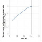 |
Figure 4: The dependence of the mass-transfer coefficient on the membrane to the permeate flow on the phase rate
|
Figure 5 presents a dependence of the mass-transfer coefficient in the membrane pores on the internal diffusion coefficient. It is seen from the Figure that as long as the process’ overall rate determines the resistance to the external mass-transfer, the process can be intensified by increasing the gas mixing intensity.
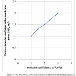 |
Figure 5: The dependence of the mass-transfer coefficient in the membrane pores on the internal diffusion coefficient
|
For the effective operation of the membranous apparatus, it is necessary to carry out preliminary processing of the gas mixture before its delivery directly to the membranous cleaning plant. It is necessary to install apparatus for the gas drying, high-efficiency separator and filter (Figure 6).
 |
Figure 6: A principal scheme of the biogas membranous cleaning
|
The biogas contains methane 58.9%(gen.) and carbon dioxide 38.6%(gen.). Its heating value is 21.2 MJ/m3.
The biogas after the cleaning contains 98%(gen.) of СН4. Н2S concentration equals to (3) 10–4 % (3-5 mln–1). Its heating value is 36.0 MJ/m3.Two-staged cleaning scheme presented in Figure 7 is offered.
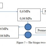 |
Figure 7: The biogas two-staged cleaning scheme |
The base flow pressure – 0,6 MPa;
Load by the base biogas – 360 m3/h;
Required surface of the membrane – 120 m2;
The plant operation period – 8000 h/year;
The membrane service life – 3 years;
Energy – 55 kW;
Methane extraction degree – 98%(gen.)
Conclusion
The experimental values of the permeability dependence on the working pressure show that the permeability depending on the pressure increases in the beginning and then becomes sensibly constant. The selectivity dependence on the pressure shows that with increase in the pressure, the selectivity decreases, as in the pressure increase, the selectivity increases by all components, i.e. decreases by the required component. The dependence of the rate effect on the permeability shows that with increase in the flow rate the air permeability increases. It is seen from the dependence of the mass-transfer coefficient on the membrane to the permeate flow on the phase rate that increase in the rate results in the mass-transfer coefficient increase. It is seen from the dependence of the mass-transfer coefficient in the membrane pores on the internal diffusion coefficient that as long as the process’ overall rate determines the resistance to the external mass-transfer, the process can be intensified by increasing the gas mixing intensity. For the effective operation of the membranous apparatus, it is necessary to carry out preliminary processing of the gas mixture before its delivery directly to the membranous cleaning plant.
References
- Baader V., Done Ye., Brennderfer M. Biogaz: teoriya i praktika (Per s nem. i predisloviye M.I. Serebryanogo) – M.: Kolos, 1982. – S.148.
- Vinogradova A.V., Kozlova G.A., Anikina L.V. Biotekhnologiya topliva: ucheb. posobiye. Perm: Izd-vo Perm. gos. tekhn. un-ta, 2008. – 212 s.
- Dominik Rutz M.Sc. Dr. Rainer Janssen. Biofuel Technology Handbook. Dipl.-Ing. WIP Renewable Energies, Sylvensteinstr. Munchen, Germany, www.wip-munich.de
- Deublein D. Steinhauser A. Biogas from Waste and Renewable Resources. Издательство: Wiley, 2008, -С.472.
- Werner Kossmann, Uta Ponitz, Stefan Habermehl, Thomas Hoerz, Pedro Kramer, B. Klingler, C. Kellner, Thomas Wittur, F. v. Klopotek, A. Krieg, H. Euler. Biogas Digest Volume II Biogas – Application and Product Development. Information and Advisory Service on Appropriate Technology. Design: UtzDornberger.
- ChristensenТ., ChristensenТ.Н., CossuR, Stegmann R. Landfilling of Waste: Biogas (Hardcover). -Publisher: Taylor & Francis; 1st ed edition, 1996. -840p.
- Concise Encyclopaedia of Bio resource Technology. CRC Press, 2004. -735р.
- Pak I.V., Tsoy R.M. Vvedeniye v biotekhnologiyu. – Tyumen: Izdatelstvo TyumGU, 2002. – S.188.
- Khigginsa I. i dr. Biotekhnologiya. Printsipy i primeneniye. – M.: Mir, 1988. – S.316.
- Mentell S.G. i Smith G. Biotekhnologiya selskokhozyaystvennykh rasteniy. – M.: Agropromizdat, 1987. – S.286.
- Biogas plants in Europe: A practical handbook. Springer. -2007. – 361 p.
- Biogas Praxis. Barbara Eder. Heinz Schulz. 2006 / perevod na rus. Biogazovyye ustanovki: prakticheskoye posobiye.
- Barbara Eder, Heinz Schulz. Biogazovyye ustanovki. Prakticheskoye posobiye. Osnovy planirovaniya. Stroitelnyye raboty. Tipy ustanovok. Ekonomicheskaya obosnovannost. // perevod s nemetskogo. – 2008 g.
- Biogaz – elektroenergiya, teplo, bioudobreniye. 11 shagov k tseli.: prakticheskoye rukovodstvo. – Tashkent, 2011.
- Dytnerskiy Yu.I., Brykov V.P., Kagramanov G.G. Membrannoye razdeleniye gazov – M.: Khimiya, 1991. – S.344.
- Kimura S. G., Walmet G. E. Separat. Sci. and Technol. -1980. Vol. 15, No4. – P. 1115-1136.
- Berry R. Chem. Eng. -1981. -No 14. -P. 63-67.
18 Simonet R- A. Desalination. -1965. –Vol.53. -P. 289 -295.
- Finken H., Bеhalau L. Chem. Ing. Tech., 1984. – Vol.56, №12. – P.944-945.
- FinkenH..Kratzig Th. Chemie-Technic., 1984. V. 13, № 8. P. 75-85.
- Schell W.J. Jur. Of Membr. Sci., 1985. V. 22, №2,3, P. 217-224.
- Tekhnologicheskiy reglament polucheniya biogaza s poligonov tverdykh bytovykh otkhodov. / Akademiya kommunalnogo khozyaystva im. K.D. Pamfilova. – M., 1990.
- Gasanova L.G., Slepova Ye.V., Mitrofanova T.I., Teplyakov V.V., Netrusov A.I., Modigel M. Polucheniye metana i vodoroda s pomoshchyu membrannykh kontaktorov, integrirovannykh s bioreaktorami. Nauchnaya sessiya MIFI-2003, Moskva, 2003: Sbornik nauchnykh trudov. T. 8.
- ST RK 2.2-2001 Poryadok osushchestvleniya gosudarstvennogo metrologicheskogo nadzora za vypuskom, sostoyaniyem i primeneniyem sredstv izmereniy, primeneniyem metodik vypolneniya izmereniy, etalonami yedinits velichin i soblyudeniyem metrologicheskikh pravil i norm.
- ST RK 2.4-98 Proverka sredstv izmereniy. Organizatsiya i poryadok provedeniya.
- ST RK 2.25-2001 Gosudarstvennyy etalon i gosudarstvennaya poverochnaya skhema dlya sredstv izmereniy temperatury.
- ST RK 2.28-2001 Gosudarstvennyy etalon i gosudarstvennaya poverochnaya skhema dlya sredstv izmereniy massy.
- ST RK 2.29-2001 Gosudarstvennyy etalon i gosudarstvennaya poverochnaya skhema dlya sredstv izmereniya dliny v diapazone ot 0,1 do 100 mm.
- ST RK 2.31-2001 Gosudarstvennyy etalon i gosudarstvennaya poverochnaya skhema dlya sredstv izmereniy izbytochnogo davleniya do 250 MPa.
- ST RK 2.33-2001 Gosudarstvennyy etalon i gosudarstvennaya poverochnaya skhema dlya sredstv izmereniy otkloneniy ot pryamolineynosti i ploskostnosti.
- GOST 8.009-84 Normirovaniye metrologicheskikh kharakteristik sredstv izmereniy.
- GOST 24104-2001 Vesy laboratornyye. Obshchiye tekhnicheskiye trebovaniya.
- GOST 7.32-2001 Otchet o nauchno-issledovatel’skoy rabote. Struktura i pravila oformleniya.
- ISO 9001 – Sistema Kachestva: Model obespecheniya kachestva pri proyektirovanii, razrabotke, proizvodstve, montazhe i obsluzhivanii.
- GOST R 52808-2007 Netraditsionnyye tekhnologii. Energetika biootkhodov. Terminy i opredeleniya.
- GOST R 53790-20101 Netraditsionnyye tekhnologii. Energetika biootkhodov. Obshchiye tekhnicheskiye trebovaniya k biogazovym ustanovkam.
- GOST 14920-79 GAZ SUKHOY Metod opredeleniya komponentnogo sostava.
- Tekhnologicheskiy reglament. Polucheniye biogaza s poligonov tverdykh bytovykh otkhodov. Otdel nauchno-tekhnicheskiy informatsii AKKh. Moskva, 1990.
- GOST 22387.2-97 Metody opredeleniya serovodoroda i merkaptanovoy sery.
- Satterfild Ch.N. Massoperedacha v geterogennom katalize. – M.: Khimiya, 1976, S.240.
- Druzyanova V.P., Petrov N. V. Tseolit i perspektivy yego ispolzovaniya pri ochistke biogaza. Severo-Vostochnyy federalnyy universitet im. M.K. Ammosova, Yakutsk.
- Rukovodstvo po biogazu. Ot polucheniya do ispolzovaniya [Elektronnyy resurs]. — Rezhim dostupa. — URL: http://esco-ecosys.narod.ru/2012_9/art272
- Feng С., Stewart W. E. – Ind. Eng. Chem. Fundam. -1973. -Vol.12, № 2. P.143- 146.
- Hesse D., Koeder L. – Chem. Eng. Sci. -1973. Vol.28, №6-7. -P.807- 811.
- Hesse D. – Chem. Ing-Tech. -1973. –Bd. 45, №3, -S.442-455.
- Krishna R. – Ind. Eng. Chem. Fundam. -1977. –Vol.16, № 2. -P.228-232.
47. Petterson G.N. Molekulyarnoye techeniye gazov. – M.: Mir, 1960. – S.272.
(Visited 321 times, 1 visits today)
This work is licensed under a Creative Commons Attribution 4.0 International License.


