

Manuscript accepted on :
Published online on: 17-12-2015
Thermochemical Heat Recovery Based on External Heat Engine
Valery Alexandrovich Kirillov1, Alexandr Valerievich Samoilov1, Alexey Borisovich Shigarov1, Denis Alekseevich Ivanov2 and Dmitry Vladimirovich Zaletov3
1Boreskov Institute of Catalysis, pr. Lavrentieva, 5, Novosibirsk, 630090, Russian Federation 2Moscow State University of Mechanical Engineering (MAMI), ul. Bolshaya Semenovskaya, 38, Moscow, 107023 Russian Federation 3Mobil GazService Ltd, per. Kholodny, 10a, Nizhny Novgorod, Nizhny Novgorod Oblast, 603000 Russian Federation
DOI : http://dx.doi.org/10.13005/bbra/1986

ABSTRACT: This work discusses the issues of thermochemical recovery as a method to improve efficiency of fuel utilization in external heat engines (EHE). The article presents thermodynamic analysis of efficiency of external thermochemical recovery (TCR) upon steam reforming of low alcohols, as well as efficiency of internal TCR upon steam reforming of methane. The issues of selection of catalysts are considered and mathematical simulation of variants of TCR solutions with regard to EHE operating by the Stirilng and Rankine cycle is performed. Variants of technical solutions of catalytic heat exchangers with external, internal and combined heat input are analyzed in thermodynamic cycles of EHE, as well as of internal combustion engines (ICE) with respect to thermochemical recovery. Variants of implementation of external and internal TCR have been studied. It is demonstrated that the most promising variants of heat recovery is the external TCR with application of oxygen-containing compounds as fuels, characterized with low point of conversion into synthesis gas (SG). A mathematical model is developed for numerical analysis of devices for TCR of heat in the combustion products of Rankine engine heater. The influence of working fluids on the cycle efficiency is analyzed, it is demonstrated that the most promising variants are gaseous carbon dioxide and ammonia.
KEYWORDS: catalyst; synthesis gas; thermochemical recovery; external heat engine; mathematical model
Download this article as:| Copy the following to cite this article: Kirillov V. A, Samoilov A. V, Shigarov A. B, Ivanov D. A, Zaletov D. V. Thermochemical Heat Recovery Based on External Heat Engine. Biosci Biotechnol Res Asia 2015;12(3) |
| Copy the following to cite this URL: Kirillov V. A, Samoilov A. V, Shigarov A. B, Ivanov D. A, Zaletov D. V. Thermochemical Heat Recovery Based on External Heat Engine. Biosci Biotechnol Res Asia 2015;12(3). Available from: https://www.biotech-asia.org/?p=2369 |
Introduction
Practical application of thermodynamic cycles of thermal machines is related with implementation of heat transfer from heating source to working fluid (WF) or heat withdrawal from it after working cycle. With regard to thermal engines, conversion of chemical energy of fuel into work is implemented in two stages: at the first stage energy is converted into heat, and at the second stage the obtained heat is converted into work. In this relation intensification of heat transfer is one of the conditions of improvement of the observed efficiency of thermodynamic cycles of thermal machines. Theoretical efficiency of reversible thermodynamic cycle is determined by the ratio of difference between average maximum temperature and average minimum temperature of heat withdrawal and does not exceed the efficiency of the Carnot cycle. Increase in the average maximum temperature is limited with thermal resistance of materials and increase with heat losses of engine into external environment. In this regard selection of WF for EHE is highly important. Decrease in average temperature of heat withdrawal is limited with environmental and engineering considerations. Due to existence of such limitations the only way to increase overall efficiency of engine is related with heat recovery of exhaust gases (EG) by means of TCR either of cogeneration.
It is known [1] that in EHE and in ICE the portion of heat energy losses withdrawn from engine with EG into environment equals to 35 %; heat transferred to cooling system: 30 %; portion of losses due to incomplete fuel combustion: about 2 %, and unaccounted heat losses reach 3 %. Theoretically, it is possible to recover heat losses related with heat withdrawal into environment and into cooling system, and thus to achieve increase in thermal efficiency. The essence of TCR is that a portion of EG heat and heat, transferred into engine cooling system, is used for endothermic conversion of initial fuel into another type of fuel possessing higher enthalpy of products. Due to this there is an increase in total efficiency of fuel utilization [2–4]. In terms of energy the most profitable solution is conversion of fuels into SG, which is a mixture of CO and Н2. The first scientific background of this method to improve EHE efficiency was given by Nosach [5], who specified it as TCR, and its practical implementation was applied to stationary solid fuel facilities.
The use of TCR makes it possible to achieve two important purposes simultaneously:
- to increase the lower heating value of reformates with regard to initial fuel. Theoretical maximum increase can reach 20–22 % upon steam reforming of propane to CO and H2 (without СО2 and especially of СН4 in the composition) [2].
- to increase stability of catalytic burning in non-adiabatic operation mode of catalytic burner (due to heat withdrawal into engine or just heat losses into environment), that is, in decreasing temperature profile in the layer of deep oxidation catalyst. Indeed, for catalytic combustion of СН4 even on the most active Pt and Pd catalysts the temperature of about 550–650°C is required. Herewith, catalytic burning of Н2 and CO can run at sufficiently lower temperature of about 200–300°С. That is, upon catalytic combustion of hydrogen-containing gas the combined area of catalytic burning and heat withdrawal can be extended into the area of lower temperatures without danger of flame failure. This provides theoretical possibility to increase significantly the useful portion of heat withdrawn into the engine.
Experimental
Efficiency of EHE and progress of thermodynamic cycle are mainly determined by selection of WF, which transfers heat in internal circuit of engines of this type.
Background of selection of working fluid
At present, as a rule in a Stirling EHE helium and hydrogen are used as WF, providing rapid heat transfer without phase transitions. Hydrogen has higher thermal conductivity and lower viscosity, which reduces losses caused by internal friction. There are numerous references, which describe advantages of WF in the form of lighter-than-air gases in order to increase output [6, 7]. Light gases have lower viscosity, which leads to decrease in consumption losses, as well as higher specific thermal capacity Ср and gas constant R.
Fig. 1 illustrates well known plot obtained upon computer simulation for a Stirling EHE designed by Philips.
![Fig. 1. Efficiency as a function of specific output for air, helium, and hydrogen [8].](https://biotech-asia.org/wp-content/uploads/2015/12/Vol12_No3_Therm_Vale_fig1-150x150.jpg) |
Figure 1: Efficiency as a function of specific output for air, helium, and hydrogen [8]. |
The values, illustrated in Fig. 1, depict that for hydrogen the efficiency is higher than for helium or air. On the other hand, helium requires less maintenance and provides higher safety. However, the use of helium or hydrogen results in some problems, among which sealing should be mentioned in particular, which is caused by high gas volatility, high cost of these gases, as well as flammability and explosiveness of hydrogen.
Recently some works were published aimed at the use of WF of high density in Stirling engines [9,10]. The use of liquid WF provides some advantages, such as:
- very high specific output of engine, resulting from high density of WF;
- sealing of liquid WF is easier and more efficient;
- liquid, being uncompressible, eliminates parasitic action of dead volume on efficiency;
- engines with liquid WF are significantly simpler and safer in operation due to insignificant amount of high pressure gas;
- the use of water or carbon dioxide as WF eliminates pollution of pumped medium, which is of peculiar interest for such industries as electronics, food industry and others.
The main drawback of the use of liquid WF in EHE is related with existence of phase transformations. A cycle of Stirling engine is closed with constant weight of WF. Under pressures below critical values for WF a Stirling engine actually operates according to the organic Rankine cycle, and due to phase transformations (evaporation–condensation) its efficiency is determined by overheating of WF, which could be applied for execution of work.
Fig. 2 illustrates the diagram of four main processes of the cycle.
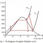 |
Figure 2: TS-diagram of organic Rankine cycle. |
Process 1–2: pressure increase of WF by means of a pump. Since at this stage the WF is liquid, it does not require for high input energy.
Process 2–3: liquid under high pressure is fed to the heated area of operating cylinder, where it is heated under constant pressure from external heating source until generation of dry saturated steam.
Process 3–3′: dry saturated steam under high pressure is still being heated in heating area of operating cylinder under constant pressure from external heating source until generation of dry saturated steam and reserve of higher amount of energy.
Process 3’–4′: dry overheated steam expands via membrane pump executing effective work. It decreases steam temperature and pressure, which can lead to partial condensation.
Process 4’–4–1: wet steam is fed to a condenser, where it is condensed under constant pressure until generation of saturated liquid. Therefore, using WF of high density it is possible to obtain gain in work amounting to additional surface area 3–3’–4’–4 due to overheating of WF.
The efficiency of engine, operating by this cycle without consideration for pump work aimed at liquid compression at the segment 1–2, can be determined by Eq. (1):
![]()
where A3′-4′ is the effective work executed at the segment 3′-4′; q1 is the supplied heat.
The work A3′-4′ can be written as Eq. (2):
where q2 is the withdrawn heat.
With consideration for Eq. (2), Eq. (1) can be rewritten as Eq. (3):
Supplied and withdrawn heat q1 and q2 can be calculated using Eq. (4):
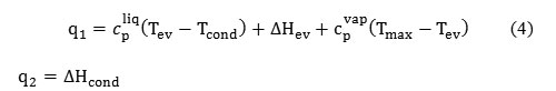
where cpliq is the integral specific thermal capacity of liquid in the temperature interval from Tev to Tcond at constant pressure, kJ/(mole K); Tev is the evaporation temperature, °C; Tcond is the condensation temperature, °C; ΔHev is the evaporation heat of WF at T = Tev (kJ); cpvap is the integral specific thermal capacity of steam in the temperature range from Tev to Tcond at constant pressure, kJ/(mole K); Tmax is the temperature in the point 3′,°C; ΔHcond is the condensation heat of WF at T=Tcond, kJ.
The value q1 according to the Hess law can be written as Eq. (5):
![]()
where cp is the average integral specific thermal capacity in the temperature range from Tcond to Tmax at constant pressure, kJ/(mole K); ΔHev is the evaporation heat of WF at T = Tcond, kJ.
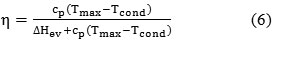
Then, ΔHev = ΔHcond. Substituting Eqs. (4) and (5) into Eq. (3), we obtain:
Now let us introduce the following designation:
![]()
where ΔHheat is the heat consumed for overheating of WF, kJ.
Dividing the numerator and the denominator in Eq. (6) by ΔHheat, we obtain Eq. (7):
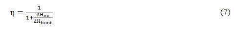
Introducing the designation ξ = ΔHev/ΔHheat, Eq. (7) can be presented as follows:
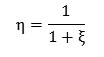
From here it follows that for achieving of maximum efficiency it is necessary to increase the portion of heat consumed for overheating of WF and to decrease the portion of heat consumed for evaporation and condensation of WF, either to select WF with low evaporation heat. Taking into account that the consumed heats of evaporation and condensation are not transferred to execution of work, promising types of WF can be liquids with minimum heat of phase transition and minimum thermal capacity in order to provide maximum overheating of WF.
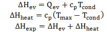
Table 1 and Fig. 3 present comparisons of calculated temperatures of overheated steam at equal thermal inputs for evaporation of 1 mole of various WF. The values of ΔHev, ΔHheat and ΔHexp were calculated as follows:
Efficiency of the Carnot cycle is determined by the equation: η = ΔTheat/ΔTmax
Table 1: Comparisons of calculated temperatures of overheated steam at equal heat consumptions for evaporation of 1 mole of various WF.
| Working fluid | Р,
bar |
Tev, °С | ΔHev, J | ΔHheat,
kJ |
ΔHexp, kJ | ΔТheat,
°С |
[eta] | [etac] |
| CO2 | 60 | 22 | 6.3 | 44.7 | 51 | 895 | 0.88 | 0.76 |
| NH3 | 20 | 67 | 23.3 | 27.7 | 51 | 602 | 0.54 | 0.69 |
| CH3OCH3 | 20 | 75.7 | 21.5 | 29.5 | 51 | 446 | 0.58 | 0.62 |
| C3H8 | 20 | 67 | 21.3 | 29.7 | 51 | 302 | 0.58 | 0.62 |
| H2O | 20 | 220 | 40.6 | 10.4 | 51 | 300 | 0.2 | 0.52 |
| CFCl3 | 15 | 130 | 25.1 | 25.9 | 51 | 295 | 0.51 | 0.52 |
| CH3OH | 20 | 166 | 38.7 | 12.3 | 51 | 224 | 0.24 | 0.45 |
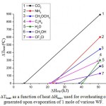 |
Figure 3: ΔTheat as a function of heat ΔHexp, used for overheating of steam generated upon evaporation of 1 mole of various WF. |
Efficiency calculation by the Rankine cycle were performed without accounting for losses due to compression of WF. This assumption is good in the region of low pressures, however, it can lead to inaccuracies under high pressures. Probably, this is related with an excess of the Rankine efficiency in comparison with the Carnot efficiency for carbon dioxide.
Therefore, the most promising WF for the Stirling engine can be carbon dioxide and ammonia with accounting for the fact that these substances have increased thermal stability in comparison with organic liquids. The least efficient WF is water. Experimental data, obtained in [10] while using water-steam system as WF for the Stirling engine, demonstrated the efficiency of heat conversion into mechanical work amounting to about 1 %, which is sufficiently low value.
Theoretical backgrounds of thermochemical recovery
As applied to EHE, it is possible to implement two types of TCR, which are conventionally designated as external and internal recovery [2]. External recovery is referred to steam conversion of fuels only due to the heat of engine EG and without recycling of EG. General layout of external TCR of heat is illustrated in Fig. 4.
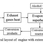 |
Figure 4: General layout of engine with external TCR of heat. |
Upon external TCR selection of fuel becomes of the highest importance. As is known, catalysts can be applied for conversion of various fuels into hydrogen-containing gas. As potential source of SG it would be reasonable to apply light homologues of saturated hydrocarbons, low alcohols and simple ethers. Selection of fuel type for generation of hydrogen is a compromise accounting for fuel value, temperature conditions of the conversion, composition of mixture after conversion and cost of catalysts for SG generation. In a series of works [2, 11-13] methanol and ethanol were selected for investigation into thermochemical recovery. An important feature, highlighting these alcohols, is low temperature of steam conversion of the mentioned alcohols and comparatively inexpensive catalysts for thermochemical conversion. The studies in [2, 11-13] solve the issues related with technical implementation of external TCR on board transport vehicle. However, they did not discuss the aspects of selection of catalysts, conditions of steam conversion of alcohols, selection of reagent type and its operational modes.
Numerous publications are available with regard to development of catalysts of steam conversion of methanol [14-17] and ethanol [18-28], esters [29] for production of SG. The most detailed studies of steam conversion of methanol were performed with copper-containing compounds, including metallic copper and its oxide, as well as other types of catalysts, the main component of which is copper in combination of oxides of other metals, such as Cu–Zn, Cu–Mn, Cu–Al, Cu–Cr and others. Above 350°C copper-containing catalysts are step-by-step deactivated as a consequence of sintering of active component. In this regard the following catalysts were prepared and studied: Cu/Al2O3–ZnO, Cu/Al2O3–Cr2O3 and Cu/Al2O3–MgO [16], catalysts in the form of amorphous alloys Cu–Zr, Cu-Zr-Pd, Cu–Zr–Au [14], as well as catalysts based on platinoids [15,16]. Summing up the published data, it should be noted that the methanol conversion was studied with the ratios of H2O/CH3OH varying from 1 to 3, GHSV = 10000–30000 ч-1 in the temperature range of 300–700°C and pressure range of 1–30 atm.
Steam conversion of ethanol was studied on applied cobalt [17–19], rhodium [18, 20-25], nickel [19, 23-25], nickel-copper [26-28] and palladium [20-22] catalysts. It was determined that in steam conversion of ethanol catalysts usually provide complete conversion at flow rates of GHSV = 5000–100000 h-1, 500–700°С and H2O/C2H5OH ratio from 2 to 14. The highest activity and stability in the steam conversion are those of catalysts based on rhodium and cobalt, the lowest value is in the case of copper and nickel.
From published experimental data on steam conversion of alcohols it follows that for copper- and nickel-containing catalysts the composition of reaction products more frequently corresponds to equilibrium values. Upon the use of rhodium- and cobalt-containing catalysts the composition of reaction products is more frequently non-equilibrium. As will be demonstrated in theoretical section, it is exactly non-equilibrium composition of reaction products that leads to increase in efficiency of fuel utilization, thus, while developing catalysts for external TCR we used rhodium- and cobalt-containing catalysts as active components.
Internal TCR is more complicated for implementation. Its essence is in endothermic catalytic steam and carbon dioxide conversion of EG in the mixture with initial motor fuel due to a portion of EG heat and heat, generated during post-combustion of oxygen in EG. Herewith, SG is generated in the composition of mixed fuel, which is further used directly in engine operating cycle. This type of conversion is referred to as tri-reforming [31–36]. Since typical composition of EG contains low amount of oxygen (СО2 = 9–10 %, Н2О = 18–20 %, О2 = 2–3 %, remainder – N2), then the EG heat and heat generated upon oxidation of initial fuel by remaining oxygen can be insufficient for endothermic reaction of steam and carbon dioxide conversion of fuel. In this case additional heat should be supplied used in the engine cooling system. General layout of internal TCR of heat is illustrated in Fig. 5.
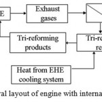 |
Figure 5: General layout of engine with internal TCR of heat. |
This layout provides for recycling of EG portion into tri-reforming reactor with addition of fuel and heat from the engine cooling system in order to maintain thermal balance.
Tri-reforming reactions are performed at higher temperatures and modified ratios between reagents, sufficiently different from the ratios applied for external recovery with the use of alcohols. In order to implement in practice the tri-reforming layout more complicated technical solutions are required, one of the main issues is selection of catalysts, determination of their resource and conditions of reactions [31–36]. Available published data, summarized partially in Table 2, show the following activity sequence of catalysts:
Ni/MgO > Ni/MgO/CeZrO2 > NiCeO2 ≈ NiZrO2 ≈ NiAl2O3 > NiCeZrO2.
Table 2: Catalysts and test conditions in tri-reforming reactions
|
# |
Catalysts | Test parameters and conditions |
Reference |
| 1 | Ni–La–CeO2 | GHSV = 30 000 h-1
T = 800°C Test duration 7.5 hours CH4/CO2/O2/H2O = 1:0.46:0.1:0.46 |
[31] |
| 2 | 5.5%Ni/CeO2;3.8%Ni/ZrO2;
6%Ni/Ce/ZrO2; 8%Ni/MgO;
6.3%Ni/MgO/Ce/ZrO2 |
Ssp = 2.2–16.8 m2/g
T = 700–850°C CH4/CO2/O2/H2O = 1:0.475:0.1:0.475 CH4/CO2/O2/H2O = 1:1:0.1:1 CH4/CO2/O2/H2O = 1:0.375:0.5:0.375 |
[32] |
| 3 | NiO/YSZ–CeO2 | Ssp = 10.2m2/g
GHSV = 10 000 h-1 T = 650–850°C Test duration 120 hours CH4/CO2/O2/H2O = 1:1:0.1:1 |
[33] |
| 4 | Ni/MgO; Ni/MgxTi1-xO | Ssp = 28–46 m2/g
T = 850°C Test duration 6 hours CH4/CO2/O2/H2O = 1:0.48:0.1:0.54 |
[34] |
| 5 | 8%Ni/Al2O3 | Ssp =367.5 m2/g
GHSV = 2000–20000 h-1 T = 750–950°C Test duration 10 hours CH4/CO2/O2/H2O = 0.5:0.125:0.25:0.125 |
[35] |
| 6 | NiO/MgO/CeO2/ZrO2/Al2O3 | T = 800°C
CH4/CO2/O2/H2O = 1:1.3:0.47:2.46 |
[36] |
Tri-reforming reactions run at 700–850°C, at this the obtainable conversions in terms of methane are at the level of 86–98%, in terms of СО2 – 55–87 %. The main issue, mentioned by all researchers, is related with propensity of nickel catalysts to coking, which restricts duration of the experiments. In order to decrease coking the systems are used with addition of lanthanum, yttrium, copper, noble metals, chromium oxide, cerium and zirconium. Nickel catalysts, applied onto oxides of alkaline metals, such as magnesium oxide, also turned to be promising variants [32-36].
Mathematical simulation of recovery unit.
The main component of recovery unit is catalytic heat exchanger, where endothermic reaction of steam conversion of hydrocarbon fuel is carried out with the aim of SG production (with subsequent use in catalytic heater) due to recovery of EG heat of engine. In the simplest variant this reactor is a tubular device into which catalyst is fed in the form of granular layer or structured metallic porous blocks, sintered with the tube wall. Ni/Al2O3 catalyst was used as a granular layer. This catalyst was characterized with low activity and propensity to methanation. Upon calculations of structured blocks it was assumed to use copper-cerium catalyst, on which in reforming of C3H8 methane is not formed. Comparison of the calculations for the mentioned catalysts made it possible to formulate requirements to catalysts, which provide maximum effect of thermochemical recovery.
Mathematical model, on the basis of which the calculations were performed, is based on the equation of heat and mass transfer obtained at the following assumptions:
- Pseudo 2D-model of the reactor is considered.
- Longitudinal dispersion of heat and substance is neglected (both for gas and catalytic layer).
- The difference between the temperatures of EG, tube wall and conversion gas is considered.
- Heat transfer (in transverse direction) from EG to tube walls, along tube radius (in the form of effective coefficient), as well as between conversion gas and catalyst with accounting for hydrodynamics, gas temperature and composition is considered.
- Mutual external and internal diffusive stopping of steam conversion of propane on catalyst is considered.
Results
Results of mathematical simulation of recovery unit
Numerical analysis based on mathematical model was aimed at calculation of distribution of temperatures and concentrations of components along the length of catalytic tube. The calculations were performed under the conditions summarized in Table 3.
Table 3: Experimental conditions. Composition of gaseous mixture С2–С4 (vol %): 14 % С2Н6, 79 % С3Н8, 7% С4Н10
| Experiment # | Experimental conditions |
| 1
(without recovery) |
hydrogen flow rate: 6 l/min; air flow rate: 70 l/min; Tin = 615°С; Tout = 458°С, противодавление 5 атм. |
| 2
(without recovery) |
hydrogen flow rate: 6 l/min; air flow rate: 70 l/min; Tin = 615°С; Tout = 458°С, backpressure: 9 atm. |
| 3
(without recovery) |
hydrogen flow rate: 6 l/min; air flow rate: 70 l/min; Tin = 615°С; Tout = 458°С, backpressure: 22.5 atm. |
| 4
(with recovery) |
hydrogen flow rate: 16 l/min, C2–C4 flow rate: 0.584 l/min;
air flow rate: 140 l/min; Tin = 800°С; Tout = 521°С |
| 5
(with recovery) |
hydrogen flow rate: 16 l/min, C2–C4 flow rate: 0.674 l/min;
air flow rate: 140 l/min; Tin = 810°С; Tout = 565°С |
While using catalyst Ni/Al2O3, the gain in heat of combustion is about 3–4 %. Such moderate gain in heat of combustion is attributed to low endothermy of the reaction due to methane generation. Nickel catalyst carries out the reaction to thermodynamic equilibrium, which at 400–500°C inevitably leads to significant concentration of methane: 25 % (on dry basis).
Using metallocene catalyst based on nickel foam, the increase in heat of combustion of reforming products can reach 17 %. More significant gain in heat of combustion is attributed to high endothermy of the reaction, since methane is not generated. Selection of active component of catalyst provides close to maximum increase in heat of combustion of propane reforming products by 17 %. At the same time, the reformer compactness is achieved due to increased thermal conductivity of metal foam carrier in comparison with catalyst granular layer.
Therefore, due to thermochemical recovery of EHE EG heat based on active structured metallocene catalyst it is possible to increase external efficiency of EHE by 17 %.
Analysis of integration of heat exchangers with EHE
In the below thermodynamic analysis four low alcohols are considered: methanol, ethanol, n-propanol and n-butanol, which are intended for the use as a source of SG production upon external thermochemical recovery. Table 4 summarizes thermodynamic data required for further analysis [37]. The following designations are used: Тboil is the boiling temperature under normal pressure, DHform (gas) is the specific heat of formation in gaseous phase, DHev is the specific heat of evaporation and Qcomb – is the lower heat of combustion (in gaseous phase).
Table 4: Certain properties of the considered alcohols [37]
|
Name |
Formula |
Тboil, °C |
DHform (gas)
Т = 25°C, kJ/mol |
DHev at
Т = 25°C, kJ/mol |
DHev at
Т=Тboil, kJ/mol |
Qcomb (alcohol)
Т = 25°C, kJ/mol |
| Methanol | СН3ОН | 65 | 201 | 37.5 | 35.3 | 677 |
| Ethanol | С2Н5ОН | 78 | 235 | 42 | 38.8 | 1279 |
| n-Propanol | С3Н7ОН | 97 | 257 | 48.3 | 41.8 | 1893 |
| n-Butanol | С4Н9ОН | 118 | 275 | 55.1 | 43.2 |
2511 |
Let us define the criterion of TCR efficiency for various alcohols as the ratio between the lower heat of combustion of mixture of thermochemical conversion products, obtained from 1 mole of alcohol, and the lower heat of combustion of 1 mole of initial liquid alcohol, let us call it the coefficient of TCR efficiency:

In order to estimate an increase in efficiency due to thermochemical conversion let us apply the data if thermodynamic calculations. The calculated values of TCR efficiency by Eq. (8) in the case of thermodynamic equilibrium composition of mixture at steam conversion of alcohols are summarized in Table 4.
From the data in Table 5 it follows that under normal pressure, 500°С, Н2О/СН4 = 2 and achievement of thermodynamic equilibrium in steam conversion of low alcohols we should expect maximum increase in TCR efficiency of not higher than 6 %. This is attributed to significant concentration of methane at output (18–24 %) and, hence, weak endothermic effect of the conversion under these conditions. Increase in conversion temperature to 700°С increases the coefficient [mu] to 16.4 % in the case of methanol and to 20.5 % in the case of ethanol. Alteration of the ratio Н2О/СН4 from 2 to 11 leads to increase in the coefficient [mu] from 3.2 to 11 % for methanol and from 5.5 to 14.6 % for ethanol.
Table 5: TCR efficiency [mu] (%) at thermodynamic at equilibrium in the reaction of steam reforming of alcohols. Conditions of calculations: Tref = 500°C, Р =1 bar, initial mole ratio Н2О/С = 2.
| Name | Composition of dry mixture after steam reforming, mol. % | Qcomb.ref.,
kJ/mol (alcohol) |
[mu], % | |||
| Н2 | CO | СО2 | СН4 | |||
| Methanol | 55.7 | 3.0 | 22.7 | 18.6 | 660 | 3.2 |
| Ethanol | 51.9 | 3.3 | 22.5 | 22.3 | 1305 | 5.5 |
| n-Propanol | 50.3 | 3.4 | 22.5 | 23.8 | 1949 | 5.6 |
| n-Butanol | 49.7 | 3.5 | 22.4 | 24.4 | 2594 | 5.6 |
| where Qcomb.ref. is the heat of combustion of reformates of one mole of alcohol | ||||||
More optimistic results can be achieved in the case when thermodynamic equilibrium is not achieved. For instance, this can be the case if such conditions and catalysts are selected, that steam conversion occurs with generation only of CO and Н2. This most energetically profitable for TCR variant of recovery corresponds to maximum endothermic effect of conversion and, hence, maximum [mu]. The calculated values of TCR efficiency for this case are summarized in Table 6.
Table 6: Stoichiometric maximum achievable gain of increase in TCR efficiency upon reforming of alcohols in SG under non-equilibrium conditions
|
Name |
Reaction | Qcomb.ref.,
kJ/mol (alcohol vapors) |
[mu], % |
| Methanol | СН3ОН = CO + 2Н2 | 768 | 20 |
| Ethanol | С2Н5ОН + Н2О = 2СО + 4Н2 | 1535 | 24.1 |
| n-Propanol | С3Н7ОН+ 2Н2О = 3СО+6Н2 | 2302 | 24.8 |
| n-Butanol | С4Н9ОН+ 3Н2О = 4СО+8Н2 | 3070 |
25 |
From the data in Table 6 it follows that in the case of thermochemical recovery under non-equilibrium conditions the value of m for certain low alcohols (starting from ethanol) varies slightly, and possible increase in TCR efficiency should be expected at about 20–25 %.
Thermodynamic analysis efficiency internal TCR
Thermodynamic analysis was performed with regard to the use of natural gas in EHE as main fuel. As applied to this case, upon tri-reforming the following chemical reactions are possible [31-36]:
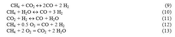
The reactions (9) – (10) are endothermic and the reactions (12) – (13) are exothermic.
The coefficient of TCR efficiency for methane is determined similar to Eq. (8) for alcohols, but without the parameter related with fuel evaporation:
where Qcomb.ref. is the lower heat of combustion of reforming products of 1 mole CH4; Qcomb is the lower heat of combustion of 1 mole CH4.
The internal TCR layout (Fig. 5) with recycling of a portion of EG was calculated for natural gas engine for the case of supply of only tri-reforming products (without mixing with auxiliary natural gas) and complete post-burning of combustible gases in EHE [2]. The coefficient of air excess [alfa], supplied to the system (EHE + TCR unit), was calculated by natural gas and varied in the range of [alfa] = 1.1–1.4. Herewith, actual coefficient of air excess with regard to the reforming products was slightly higher than the calculated coefficient [alfa] due to auxiliary air in EG used for recycling. Composition of the mixture at the outlet of tri-reforming reactor was determined on the basis of the condition of thermodynamic equilibrium at reactor outlet at 550–700°С. Taking into consideration that the temperature of EG, withdrawn for recycling, can be significantly lower, that is, 350–600°С, as well as the condition that cumulative thermal effect of tri-reforming should be endothermic (otherwise, the TCR efficiency [mu] < 0), then in order to maintain the required temperature level in the reactor it was proposed to apply supplemental recovery of heat withdrawn into the engine cooling system.
Since for the TCR layout, illustrated in Fig. 5, the mixture composition at input to the engine depends on amount of supplied initial fuel, ratio of conversion products after tri-reforming reactor determined by recycling, content of components of EG portion, then the stationary values of material balance of this layout were determined by iteration method.
Calculated results of coefficient of efficiency of TCR by Eq. (7) at the temperature of 700°С at output of tri-reforming reactor as a function of portion of EG supplied for recycling frec, and coefficient of air excess [alfa], supplied to EHE, are illustrated in Fig. 6.
![Fig. 6. TCR efficiency coefficient as a function of EG portion sent to recycle frec at various coefficient of air excess for natural gas EHE [alfa] = 1.4 (curve 1), [alfa] = 1.2 (curve 2), [alfa] = 1.1 (curve 3). Tri-reforming temperature: 700°С.](https://biotech-asia.org/wp-content/uploads/2015/12/Vol12_No3_Therm_Vale_fig6-150x150.jpg) |
Figure 6: TCR efficiency coefficient as a function of EG portion sent to recycle frec at various coefficient of air excess for natural gas EHE [alfa] = 1.4 (curve 1), [alfa] = 1.2 (curve 2), [alfa] = 1.1 (curve 3). Tri-reforming temperature: 700°С. |
Similar results upon varying of temperature and constant coefficient of air excess [alfa] = 1.1 are illustrated in Fig. 7. The figures distinctly show existence of maximum at variation of frec.
![Fig. 7. TCR efficiency coefficient as a function of EG portion sent to recycle frec at various output temperature of tri-reforming reactor: 550°С (curve 1), 600°С (curve 2), 700°С (curve 3). Coefficient of air excess for natural gas EHE [alfa] = 1.1.](https://biotech-asia.org/wp-content/uploads/2015/12/Vol12_No3_Therm_Vale_fig7-150x150.jpg) |
Figure 7: TCR efficiency coefficient m as a function of EG portion sent to recycle frec at various output temperature of tri-reforming reactor: 550°С (curve 1), 600°С (curve 2), 700°С (curve 3). Coefficient of air excess for natural gas EHE [alfa] = 1.1. |
Existence of maximum in these curves is attributed to the fact that EG contains oxygen, which at constant flow rate of natural gas at the input to tri-reforming reactor and increasing recycling of EG burns up methane, thus leveling the effect of endothermic conversion of tri-reforming. In other words, the existence of maximum is stipulated by alteration of ratio between endothermic and exothermic stages of tri-reforming. Indeed, increase in efficiency of internal recovery is provided only by endothermic reactions and increase in supply of EG to tri-reforming reactor in fact leads to increase in oxygen flow rate and increasing contribution of endothermic reactions. This effect is confirmed by calculation of thermal output of exothermic and endothermic stages at [alfa] = 1.1, Tref = 6000C, as well as by calculations of cumulative thermal output of tri-reforming with minimum in the point of optimum portion frec = 0.38 (Fig. 8).
![Fig. 8. Thermal power (kW) of exothermic stages of Qox (curve 1), endothermic stages Qref (curve 2) and cumulative thermal power Qtot (curve 3) upon tri-reforming as a function of EG portion returned to recycle frec. Calculations were performed at flow rate of natural gas to tri-reforming reactor 1 m3/h, [alfa] = 1.1, Tref = 600°C.](https://biotech-asia.org/wp-content/uploads/2015/12/Vol12_No3_Therm_Vale_fig8-150x150.jpg) |
Figure 8: Thermal power (kW) of exothermic stages of Qox (curve 1), endothermic stages Qref (curve 2) and cumulative thermal power Qtot (curve 3) upon tri-reforming as a function of EG portion returned to recycle frec. Calculations were performed at flow rate of natural gas to tri-reforming reactor 1 m3/h, [alfa] = 1.1, Tref = 600°C. |
The mixture composition after tri-reforming for this optimum point corresponds to such composition (mol %): СН4 = 2.47, СО2 = 6.59, CO = 8.14, Н2 = 22.39, Н2О = 7.06, N2 = 53.35. With the aim of comparison we show the mixture composition (mol %) after tri-reforming reactor for another optimum point (at [alfa] = 1.4, Tref = 7000C, frec = 0.17): СН4 = 4.18, СО2 = 1.15, CO = 17.47, Н2 = 35.71, Н2О = 1.51, N2 = 39.98.
Therefore, in the frames of layout with internal TCR and recycling of EG there exists optimum portion of EG frec, withdrawn for recycling. The value of this optimum portion at 1.1 < [alfa] < 1.4, 550°С < Tref < 700°С is in the range 0.17 < frec < 0.42. From here it follows that the higher is the coefficient of air excess a and the higher is the reforming temperature, the lower portion of EG should be returned for recycling.
Discussion
Nowadays attention of numerous researchers is attracted by the issue of thermochemical recovery, which is one of the methods to improve of efficiency of fuel utilization in EHE. In order to solve this problem the conditions of TCR of oxygen-containing fuels in SG were analyzed thermodynamically aiming at determination of composition of converted mixture which could provide maximum efficiency.
The essence of TCR is that a portion of EG heat and heat, transferred to engine cooling system, is used for endothermic conversion of initial fuel into another fuel type with higher enthalpy of products, thus providing corresponding increase in efficiency of fuel and EHE in total.
There are several variants of implementation of external and internal TCR. The external recovery refers to the steam conversion of fuels only by means of EG heat of engine without recycling of EG. In the case of internal recovery together with the EG heat of engine steam and carbon dioxide conversion of initial fuel with EG products is (fuel tri-reforming).
It should be mentioned that internal TCR can be referred to the most promising methods of heat recovery, which utilizes oxygen-containing compounds with low points of conversion into SG as a fuel.
Conclusions
- Aimed at a solution of the issue of TCR as a method to improve efficiency of fuel utilization in EHE, thermodynamic analysis of the TCR conditions of oxygen-containing fuels in SG has been performed. It is illustrated that for achievement of maximum efficiency the composition of converted mixture should be non-equilibrium and shifted to higher concentration of H2 and СО2.
- Variants of technical solutions for catalytic heat exchangers with external, internal and combined heat input in thermodynamic cycles of EHE and ICE has been performed with regard to TCR.
Variants of implementation of external and internal TCR have been studied. It is demonstrated that the most promising variant of heat recovery is external TCR with application of oxygen-containing compounds as fuels, characterized with low point of conversion into SG. Herewith, the achievable effect of increase in the efficiency of fuel combustion can reach 17 %.
Upon internal recovery the reactions of tri-reforming run at higher temperatures and at modified ratios between reagents, sufficiently different from the ratios applied for external recovery with the use of alcohols. Therefore, upon practical implementation of tri-reforming more complicated technical solutions are required; one of the main issue is the selection of catalysts, determination of their resource and reaction conditions.
3. A mathematical model has been developed for numerical analysis of devices for TCR of heat in the combustion products of Rankine engine heater. It has been applied for analysis of thermodynamic cycle in the variant of organic Rankine cycle. It is demonstrated that in order to achieve maximum efficiency of the cycle it is necessary to increase the heat portion applied for overheating of WF; to decrease the heat portion applied for evaporation and condensation of WF, either to select WF with low evaporation heat. Taking into account that the consumptions for evaporation heat and condensation do not transfer to execution of work, promising types of WF can be liquids with minimum heat of phase transition and minimum thermal capacity for provision of maximum overheating of WF. The influence of WF on the efficiency of cycle has been analyzed, it is demonstrated that the most promising variants are gaseous carbon dioxide and ammonia, with consideration for their increased thermal stability in comparison with organic liquids.
Acknowledgments
This work was performed in the frames of Agreement on grant dated June 5, 2014, No, 14.577.21.0071 (Unique identifier of applied research (project) RFMEFI57714X0071) with support from Ministry of Education and Science of Russian Federation.
References
- Internal combustion engines. Theory of piston and combined engines. (1983). Edited by Orlin, A.S. and Kruglov, M.G. Moscow. Mashinostroenie.
- Kirillov, V.A., Shigarov, A.B., Kuzin, N.A., Kireenkov, V.V., Amosov, Yu.I., Samoilov, A.V., Burtcev, V.A. (2013). Fuels thermochemical reforming into hydrogen synthesis gas by internal combustion engines heat recuperation. Theoretical Foundations of Chemical Engineering, v.47, #5 (46), p.503-517.
- Ipatov, A.A., Kamenev, V.F., Khripach, N.A., Lezhnev, L.Yu. (2007). Development and research of vehicles with various types hydrogen and combined energy units. Journal of automobile engineers, #5 (46), p.18.
- Fomin, V.M., Kamenev, V.F., Khripach, N.A. (2005). Adjustment of working cycle of ICE with compulsory ignition and thermochemical regeneration of rejection heat. Education through science: Coll. of w. of the int. symposium. Moscow. Bauman Moscow State Technical University, p. 142.
- Nosach, V.G. (1967). Methods for increase efficiency of fuel using in technology processes. Thermal physics and heat engineering. #7, p.44.
- Hoseman, G., Cerini, W.G. (1974). On-board generator supplies H2 for I-C engine. Automotive Engineering, v. 82. #8, p. 42.
- Thombare, D. G., Karmare, S. V. (2012) Theoretical and experimental investigation of Alfa type bio mass Stirling engine with effect of regenerator effectiveness, heat transfer, and properties of working fluid. Journal of Renewable Sustainable Energy, v. 4, p. 043126-043139.
- Onovwiona, H.I., Ugursal, V.I. (2006). Residential cogeneration systems: review of the current technology. Renewable and Sustainable Energy, Reviews, v. 10, #5, p. 389-431.
- Glushenkov, M., Sprenkeler, M., Kronberg, A., Kirillov, V. (2012). Single-piston alternative to Stirling engines. Applied Energy, v. 97, p.743–748.
- Kirillov, V.A., Kireenkov, V.V., Kuzin, N.A., Samoilov, A.V., Shigarov, A.B. (2015). Catalytic external heat engine. Theoretical Foundations of Chemical Engineering, v.49, #4, p. 394-406.
- Allen, J., Soinski, A., Koyama, K. (2011). Thermochemical fuel reforming for reciprocating internal combustion engines. PIER final project report of Gas technology Institute, CEC-500-2009-011. GTI. 2011. p. 35.
- Ouchi, T. (1986). Alcohol reforming device. Patent JP61141927.
- Amphlett, J.C., Evans, M.J., Jones, R.A., Mann, R.F., Weir, R.D. (1981). Hydrogen production by the catalytic steam reforming of methanol. The Can. J. of Chem. Eng. v.59, #6. p. 720.
- Suwa, Y., Ito, S., Kameoka, S., Tomishige, K., Kunimori, K. (2004). Comparative study between Zn-Pd/C and Pd/ZnO catalysts for steam reforming of methanol. Appl. Cat. v. 267. p. 9.
- Suwa, Y., Ito, S., Kameoka, S., Tomishige, K., Kunimori, K. (2003). Steam reforming of methanol over Pt–Zn alloy catalyst supported on carbon black. Cat. Commun. v. 4, p. 499.
- Sekizawa, K., Utaka, T., Eguchi, K. (1999). Catalytic production of hydrogen from methanol for fuel cell application. Kinetics and Cat. v. 40, #3, p. 411.
- Liguras, D.K., Kondarides, D.I., Verykios, X.E. (2003). Production of hydrogen for fuel cell by steam reforming of ethanol over supported noble metal catalysts. App. Cat. v. 43, #4, p. 345.
- Aupretre, F., Descorme, C., Duprez, D., Casanave, D., Uzio, D. (2005). Ethanol steam reforming over MgxNi1–xAl2O3 spinel oxide-supported Rh catalysts. J. Cat. v. 233, p. 464.
- Frusteri, F., Freni, S., Spadaro, L., Chiodo, V., Bonura, G., Donato, S., Cavallaro, S. (2004). H2 production for MC fuel cell by steam reforming of ethanol over MgO supported Pd, Rh, Ni and Co catalysts. Cat. Commun. v. 5, p. 611.
- Lee, S., Ahmed, S., Ahluwalia, R. (2006). Steam reforming of ethanol at elevated pressure for hydrogen production. Proc. 2006 Fuel Cell Seminar, November 13–17. Hawaii. Rep. 000401.
- Llorca, J., de la Piscina, P.R., Dalmon, J-A., Sales, J., Homs, N. (2003). CO-free hydrogen from steam-reforming of bioethanol over ZnO-supported cobalt catalysts. Effect of the metallic precursor. App. Cat. v. 43, #4, p. 355.
- Batista, M. S., Santos Rudye, K. S., Assaf Elisabete, M., Assaf José, M., Ticianelli Edson, A. (2004). High efficiency steam reforming of ethanol by cobalt-based catalysts. J. of Power Sources, v. 134, p. 27.
- Kaddouri, A., Mazzocchia, C. (2004). A study of the influence of the synthesis conditions upon the catalytic properties of Co/SiO2 or Co/Al2O3 catalysts used for ethanol steam reforming. Cat. Commun. v. 5, p. 339.
- Batista, M.S., Santos Rudye, K. S., Assaf Elisabete, M., Assaf José, M., Ticianelli Edson, A. (2003). Characterization of the activity and stability of supported cobalt catalysts for the steam reforming of ethanol. J. of Power Sources, v. 124, p. 99.
- Freni, S. (2001). Rh based catalyst for indirect internal reforming ethanol application in molten carbonate fuel cells. J. of Power Sources, v. 94, p. 14.
- Frusteri, F., Freni, S., Chiodo, V., Spadaro, L., Di Blasi, O., Bonura, G., Cavallaro, S. (2004). Steam reforming of bio-ethanol on alkali-doped Ni/MgO catalyst: hydrogen production for MC fuel cell. Appl. Cat. v. 270, #1–2, p. 1.
- Srinivas, D., Satyanarayana, C.V.V., Potdar, H.S., Ratnasamy, P. (2003). Structural studies on Ni–CeO2–ZrO2 catalyst for steam reforming of ethanol. Appl. Cat., v. 246, #2, p. 323.
- Freni, S., Cavallaro, S., Mondello, N., Spadaro, L., Frusteri, F. (2003). Production of hydrogen for MC fuel cell by steam reforming of ethanol over MgO supported Ni and Co catalyst. Cat. Commun., v. 4, #6, p. 259.
- Meshcheryakov, V.D., Kirillov, V.A. (2000). Analysis of thermodynamic equilibrium of reaction of dimethyl ether receiving from syngas. Theoretical Foundations of Chemical Engineering, v.34, #1, p.92.
- Kirillov, V.A., Meshcheryakov, V.D., Sobyanin, V.A., Belyaev, V.D., Amosov, Yu.I., Kuzin, N.A., Bobrin, A.S. (2008). Bioethanol as a perspective fuel for fuel cells energy plants. Theoretical Foundations of Chemical Engineering, v.42, #1, p.3.
- Pino, L., Vito, A., Cipiti, F., Lagana, M., Recupero, V. (2011). Hydrogen production by methane tri-reforming process over Ni–ceria catalysts: Effect of La-doping. Appl. Cat. v.104, p. 64.
- Song, C., Pan, W. (2004). Tri-reforming of methane: a novel concept for catalytic production of industrially useful synthesis gas with desired H2/CO ratios. Catalysis Today. v. 98, p. 463.
- Kang, J.S., Kim, D.H., Lee, S.D., Hong, S.I., Moon, D.J. (2007). Nickel-based tri-reforming catalyst for the production of synthesis gas. Appl. Cat. v. 332, p. 153.
- Jiang, H., Li, H., Yi, Z. (2007). Tri-reforming of methane to syngas over Ni/Al2O3 – thermal distribution in the catalyst bed. J. Fuel Chem. Technol. v.35, P. 72.
- Jiang, H., Li, H., Xu, H., Zhang, Y. (2007). Preparation of Ni/MgxTi1-xO catalysts and investigation on their stability in tri-reforming of methane. Fuel Proc. Technol. v. 88, p. 988.
- Aboosadi, Z.A., Jahanmiri, A.H., Rahimpour, M.R. (2011). Optimization of tri-reformer reactor to produce synthesis gas for methanol production using differential evolution method. Appl. Energy. v. 88, p. 2691.
- Reed, R., Prausnitz, J., Sherwood, T. (1982). Properties of gases and liquids. Leningrad. Chemistry.

This work is licensed under a Creative Commons Attribution 4.0 International License.


