

Manuscript accepted on :
Published online on: 13-01-2016
The Creation of A Neutralization System for A High-Efficiency Gas Engine
Vladislav Anatolievich Luksho1, Andrey Victorovich Kozlov2, Vadim Fedorovich Kutenev3 and Vladimir Ivanovich Panchishniy4.
1Head of department, Doctor of philosophy. Federal State Unitary Enterprise Central Scientific Research Automobile and Automotive Institute "NAMI" (FSUE “NAMI”), Avtomotornaya street, 2, Moscow, Russia, 125438. 2Head of department, Doctor of engineering.Federal State Unitary Enterprise Central Scientific Research Automobile and Automotive Institute "NAMI" (FSUE “NAMI”), Avtomotornaya street, 2, Moscow, Russia, 125438. 3Director of Centre, Doctor of engineering.Federal State Unitary Enterprise Central Scientific Research Automobile and Automotive Institute "NAMI" (FSUE “NAMI”), Avtomotornaya street, 2, Moscow, Russia, 125438. 4Senior Researcher, Doctor of philosophy.Federal State Unitary Enterprise Central Scientific Research Automobile and Automotive Institute "NAMI" (FSUE “NAMI”), Avtomotornaya street, 2, Moscow, Russia, 125438.
DOI : http://dx.doi.org/10.13005/bbra/1971

ABSTRACT: The article covers aspects of creation of a neutralization system for a new generation high-efficiency gas engine. It provides the results of works on achieving high power and economic performances of an engine. The description of a bifunctional neutralization system is presented along with the results of works on achieving effective functioning of the neutralization system.
KEYWORDS: gas engine; miller cycle; natural gas; internal combustion engines; aftertreatment system; nitrogen oxides; three-way catalyst; selective catalytic reduction
Download this article as:| Copy the following to cite this article: Luksho V. A, Kozlov A. V, Kutenev V. F, Panchishniy V. I. The Creation of A Neutralization System for A High-Efficiency Gas Engine. Biosci Biotechnol Res Asia 2015;12(3) |
| Copy the following to cite this URL: Luksho V. A, Kozlov A. V, Kutenev V. F, Panchishniy V. I. The Creation of A Neutralization System for A High-Efficiency Gas Engine. Biosci Biotechnol Res Asia 2015;12(3). Available from: https://www.biotech-asia.org/?p=3748 |
Introduction
Natural gas is the most considerable alternative for liquid petroleum-derived motor fuels. In the Russian Federation the fleet of vehicles that operate on compressed natural gas (CNG) amounts to about 100 000 vehicles. In the nearest term this amount is going to grow essentially, mainly due to increase in a share of buses and municipal vehicles that operate on natural gas. For this type of motor vehicles the use of gas fuel will be the most effective.
Considering that the aspects of economic feasibility are of prime importance in case of transition to alternative fuels, achievement of high fuel efficiency of gas engines is a fundamental condition for success in expansion of gas fuels application.
The main part
Use of gas fuels in motor vehicles is connected with solving technical problems of converting gasoline and diesel engines into the engines, capable of working on gas fuel. Gasoline engines may only be converted into gas versions by installation of an additional gas feed system. Mainly it is done for the engines installed on motor vehicles with total mass up to 3.5 tons. At the same time possibility of work on gasoline as well remains.
Gas engines with spark ignition for motor vehicles with total mass exceeding 3.5 tons are created by converting diesel engines. As a result, the engine design undergoes significant changes, and engines can work on gas fuel only.
The most widespread, and, as for today, almost the only possible solution for converting diesel engines in all-gas ones is a method of modification of a compression ratio by replacing a piston block (Akira et al., 2003, Lauderdale, 2010). Upon that the geometrical compression ratio is taken in a range of 10.5 – 13.0 units. Reduction of the compression ratio leads to drop of indicated efficiency coefficient of the gas engine in comparison to the basic diesel engine. And the increase of throttling losses leads to drop of efficency coefficient, on average and small loadings. All this leads to aggravation (up to 30 %) of operational consumption of gas fuel (in volume units) in a gas engine vehicle, in comparison to a diesel analogue.
Such method of fuel efficiency improvement as application of a Miller cycle, realised in gasoline engines and in stationary gas engines (Arata et al., 2011, Endo et al., 2001, Miller, 1947, Zhao and Chen, 2007) seems prospective.
Results of the calculation research conducted by the authors, have proved possibility of significant improvement of fuel efficiency of a gas engine converted from a diesel engine due to the use of shortened intake and exhaust strokes, upon retention of a high geometrical compression ratio (Luksho et al, 2011, Luksho, 2012, Luksho et al, 2015).
Realization of a cycle with the shorter intake and exhaust strokes in a high-power high-pressure charging gas engine requires solving three interconnected tasks:
- creation of a new camshaft with modified phases of an open positon of intake and exhaust valves;
- creation of a feed and air supply system, choosing a pressure-charging system with high values of pressure of inlet air;
- creation of an exhaust gas neutralization system in order to meet modern requirements as to the hazardous substances emissions.
During the shorter intake stroke with early valve closing during cam profiling (forming) the requirements of non-impact work of a gas distribution mechanism shall be met.
During calculations of a cam profile with an account to technological restrictions it was defined, that the largest possible angle of the intake valve’s open position amounts to 135 °-145 ° of a crankshaft angle. At the same time the angle of the intake valve closing shall not exceed 120 ° after UDC, which corresponds to a compression ratio of about 13.5 – 14 units. A number of camshaft variants with various strategies of the Miller cycle implementation were designed, including that with a shorter exhaust stroke, in order to give an experimental evaluation to these variants and find a solution for the aspect of choosing a strategy for a pilot sample of an engine.
The task was to develop a variant which would allow to shorten the intake stroke to the required At values, while retaining allowable loads in gas distribution mechanism and at minimum reduction of time-section. It was established that for the given kinematic diagram it might be accomplished by use of a concave cam profile.
In order to evaluate the profile working capacity, calculations of maximum contact voltage in the area of a cam-follower contact were carried out. Based on the results of preliminary calculations of accelerations and forces applied to the gas distribution mechanism, it was defined that the maximum force applied to the follower roller increased from 2 000 N to 4 000 N, i.e. two times. Calculations showed that a correct choice of a material of the follower mechanism will help to avoid excessive wear in the cam-follower contact.
At the same time, following the reduction of effective ratio for amplification of the prolonged expansion effect, the exhaust stroke was also reduced due to the delayed exhaust valve opening.
As a result of the carried out calculations, the following two variants of gas distribution phases and camshafts’ cam profiles were suggested for realization (Figure 1):
Shaft No 1: intake valve, shortened phase – open position phase width – 141,4° crankshaft angle (21,4° before UDC + 120° after UDC), cam height – 6,0 mm, maximum valve lift – 7,94 mm);
Exhaust valve – no modifications.
Shaft No 2: – intake valve – similar to the variant No 1;
Exhaust valve, shortened phase – open position phase width 221,9° crankshaft angle (20,2° before BDC + 180° + 21,7° after BDC), height 7,86 mm, maximum valve lift 10,4 mm).
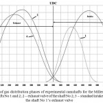 |
Figure 1: Diagram of gas distribution phases of experimental camshafts for the Miller cycle realization 1 – Intake valve of the shafts No 1 and 2; 2 – exhaust valve of the shaft No 2; 3 – standard intake valve; 4 – standard and the shaft No 1’s exhaust valve |
Exterior speed characteristic of an engine after works on choice of a turbocharging system and a feed system are given in the Figure 2.
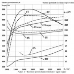 |
Figure 2: Exterior speed characteristics of a gas engine 1T – torque with the shaft No 1; 2T – torque with the shaft No 2; 1EGT – exhaust gases temperatures before a turbine with the shaft No 1; 2EGT – exhaust gases temperatures before a turbine with the shaft No 2; 1S – specific gas consumption with the shaft No 1; 2S – specific gas consumption with the shaft No 2; 2О – optimal ignition advance angles; 2A – ignition advance angle at which detonation takes place. |
Analysis of works conducted by a number of researches has shown that detonation in a gas engine with the high compression ratio is a significant problem (Li and Karim, 2006, Parks II et al, 2007). In the designed gas engine there was no detonation on all operating modes at intake air temperatures up to 80C.
The maximum engine power of 180 kW (Torque = 750 Nm at the frequency rate 2300 min-1) was achieved with two variants of camshafts. The optimal ignition advance angle is defined in accordance with maximum torque, but with restrictions with two conditions. First, no exhaust gases temperature increase more than 750 – 800°С before the turbine is allowed; second, no detonation is allowed.
These restrictions did not allow to achieve high torque values at average rotation rates with the shaft No 1. It shall be noted that the main advantage of the shaft No 2 is in the possibility to reduce exhaust gas temperature at average by 85-110°С at the same filling parameters.
Use of the camshaft No 2 that performs the operating process with shortened intake and exhaust strokes provided the engine power characteristics on the basic diesel engine level without any signs of breakdowns in the operating process. Another advantage is the reduction of specific fuel consumption for the entire speed characteristic. In the course of testing of six engines for two years there had been no signs of excessive wear.
The further works on the engine development were aimed at creation of the exhaust gas neutralization system.
NAMI’s studies as well as studies of other researchers note that in the process of converting of a diesel engine into a gas one with spark ignition quite high level of methane emissions, many times exceeding the existing standards. (Kalam et al., 2008, Kinnunen et al., 2009). Inertness of methane is explained by its high strength, low polarity of a С–Н bond and rigidity of tetrahedral structure that obstructs activation of СН4 molecule.
Higher strength of the C-H bond in methane makes the process of its oxidation more complicated and serves as the main reason for higher hydrocarbon emission, which usually exceeds the permitted level substantially (Petersen et al., 2007). In order to comply with the modern standards as to the CO and hydrocarbons emissions, a catalytic converter is required that ensures effective afterburning of methane and other hydrocarbons at average by 80-90% at the most common exhaust gas temperatures of a gas engine (350-500°С). For these purposes catalysts with the advanced concentration of palladium that three and more times exceeds content of active metal in common converters for engine and diesel engines.
As it is known, depending on the applied air excess ratio as well as on composition, flow and temperature of combustion products, different neutralization systems are used (Parks II et al, 2007). If an engine works on stoichiometric mixtures, three-way systems (TWS) are used; and if it works on lean (diluted) mixtures – than systems that combine functions of oxidation of uncomplete combustion products – CO and particularly methane and selective catalytic reduction of nitrogen oxides (SCR-technologies) are used. It is worth noting that in a number of cases a three-way catalyst may successfully perform an oxidation function, which considerably simplifies the structure of the gas engine neutralization system with the sufficiently wide range of fuel-air mixture composition modification.
Afterburning of toxic components of a gas ICE at λ>1 requires use of converters, the construction of which implies a modular principle that allows to create systems which ensure neutralization of nitrogen oxides and methane in the presence of excess of oxygen (Smith and Bartley, 2007, Tena et al., 2007, Wang et al., 2007, Millo and Ferrano, 1998). These systems combine components with oxidating and reductive functions in accordance with temperature, concentration and proportion of toxic components and oxygen. For neutralization of СН4 oxidating catalysts are sued; for NOx (> 90%) neutralization – either SCR-converters (high concentrations of nitrogen oxides), or a “catch” with self-regenerating sorbent-catalyst (low concentrations). It is important that in a number of cases it is expedient to use reduction of nitrogen oxides as well that at the excess of oxygen proceeds in the presence of reducing agents (such as ammonia, hydrogen, carbon monoxide, hydrocarbons or their mixtures) only. Composition of catalytic contacts for selective reduction of nitrogen oxides is defined by the reducing agent nature.
A number of catalysts that are capable of effective provision of methane oxidation and reduction of nitrogen oxides in a wide temperature range was defined for exhaust gases neutralization in an ICE. The key components of three-way catalysts of the exhaust gases neutralization in an ICE working on natural gas, are platinum group metals with additional promotion by oxides Се, Zr and some of REEs, added for boost of efficiency and thermal stability of the contact (Nikolaenko et al., 2011, Terenchenko et al.,2015).
In order to provide effective exhaust gases purification from СН4 at temperatures below 300-350°С that are common for urban traffic in a stop-start mode, TWC-converter shall be added with a highly-efficient in the methane oxidation reaction catalyst, e.g. palladium catalyst. Combining a traditional three-way converter with a self-regenerating sorbent-catalyst of nitrogen oxides allows to boost convertion of NOx at minimal loads, e.g. on a high-speed highway or during long drives.
Of course, a gas engine work on diluted mixtures may have a positive effect on boosting the fuel efficiency, but the neutralization system with use of SCR-technologies is more expensive and requires additional operational expenditures. The preliminary calculations for the engine under development have shown that in terms of initial expenditures, operational expenditures and fuel efficiency, preference shall be given to the variant with use if TWC system.
On the basis of the FSUE NAMI’s experience in creation of complex neutralization systems for a wide range of engines with operating capacity from 0.3 to 17.4 litres and power from 5 to 800 kW, the requirements to the neutralization system of a gas engine working on stoichiometric mixtures were developed. Ceramic or metal units with channel density 20÷60 cells/sm2 were used as a primary carriers, on which a second carrier on the basis of ceria or aluminium zirconium oxide, and catalytic contacts mainly on the basis of platinum group metals Pt-, Pd-, Pt-Pd, Pd-Rh, Pt-Pd-Rh was applied depending on a type of a converter. Thermal air gaps with thermal conductivity on the level of 0.041W/mК, or high temperature insulating fibres (e.g. mulita silica fibre), fabrics or other insulating materials, such as vermiculite with a thermal conductivity coefficient is 0,050-0,085W/mK, were used to maintain optimal temperature mode in catalytic reaction zones in the constructions under analysis.
Another important parameter is volume velocity which is usually viewed as a ratio of exhaust gases flow per hour to a catalyst capacity and which characterizes permissible gas load on the catalyst. Since the exhaust gases temperature on idle modes and low loads does not exceed 300-350°С, when designing a converter it is necessary to use a catalyst that ensures purification of methane on volume capacities up to 100.0 hour-1. According to the FSUE NAMI specialists’ calculations, catalytic load volume of a three-way catalyst for a gas engine shall be approximately close to cylinders volume. When HVAC-systems are used, after urea feed, the volume of catalytic load based on titanium-vanadium composition with additional wolfram doping increases by 50 %. On the basis of the conducted studies, technical requirements to three-way (TWC) converters were developed; the converters were manufactured at MTC MCP OJSC and tested within the an exhaust system of the created in FSUE NAMI gas engine mod. 821.10.
Structurally a bifunctional converter is a cylindrical body with a catalyst inside. Between the body and the catalyst there is a sealing gasket, complex hydroalumosilicate on the basis of vermiculite, a characteristic feature of which is increase of volume during heating (15-20 times), which causes secure fixation of a catalyst in the converter’s body. Besides, vermiculite has high heat insulating properties, which is quite important for maintenance of optimal temperatures in the catalytic reaction zone.
Intake and exhaust zones of the converter consist of cones with approximately 50° angles between a cone generatrix and an axis, and connecting flanges for coupling with the cylindrical body and exhaust system. Such structure provides rather uniform velocity profile at the input to the catalyst, allows to change catalysts timely and to use special measuring units to control composition, temperature and pressure difference on the catalyst.
The rest of the system’s elements – an oxygen sensor and a control unit are regular components of the engine mod. 821.10, while the measuring system, which includes a set of sensors that provide information on exhaust gases flow, toxic components concentration, temperatures and pressure difference along the gas movement path in catalytic elements and system of registration and processing of information, was specifically designed to study processes in the neutralization system.
As a result, of the conducted research, the zone of effective operation of the used converter (Figure 3) was defined, and the algorithms of the feed system elements that ensure complex reduce of hazardous substances emissions with exhaust gases, nitrogen oxides in particular, were finished. The zone of 90% bi-functionality of the tested converter is in a quite narrow range of mixture compositions 0,97 – 0,99, i.e. the required accuracy of mixture compositions does is no more than 2%.
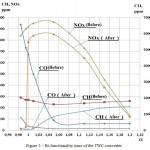 |
Figure 3: Bi-functionality zone of the TWC-converter |
Table 1: Hazardous substances emissions during testing on the ESC cycle
| Parameter | Hazardous substances emissions | ||
| СО | THC+СН4 | NOx | |
| (mg/Kwh) | |||
| Gas engine mod.821.10 | |||
| Measured values of the parameters | 1.23 | 0.16 | 0.095 |
| Values of the parameters with regard to the degradation factor – DF | 1.35 | 0.17 | 0.1 |
| Degradation factors DF | 1.1 | 1.05 | 1.05 |
| Regulatory values В2 | 1.50 | 0.46 | 2.0 |
Degree of purification on the ESC cycle modes amounts to 85-92%.
After correction of the engine control unit software, the test on the ETC cycle were conducted in accordance with the testing procedure of UNECE Regulations No 49-05. The results of the testing confirmed compliance with EURO-5 ecological class regulations with large margins as to CO and NOx emissions.
Conclusions
Evaluation of hazardous substances emissions from gas engines as to compliance with regulations of UNECE Regulations No 49-05 (Euro 5) is performed on the ETC cycle. However, for preliminary evaluation of the TWC-converter efficiency as to the degree of purification, and in order to develop the engine control system, it was performed on the ESC cycle (on the set modes). The tests results are given in the table 1.
Acknowledgments
The paper was prepared under the agreement # 14.624.21.0005 with the Ministry of Education and Science of the Russian Federation (unique project identifier RFMEFI62414X0005) to create an experimental model of the system of neutralization of toxic components.
References
- akira tsunoda, hiromi shimoda, tatsuo takaishi, (2003). MITSUBISHI Lean-burn Gas Engine with World’s Highest Thermal Efficiency. Mitsubishi Heavy Industries, Ltd. Technical Review, 4 (40).
- Lauderdale F. (2010). Engine Technology and Corporate Overview. The Compelling Case for Natural Gas Vehicles.
- Arata, J. et al. (2011). Backward-Looking Simulation of the Toyota Prius and General Motors Two-Mode Power-Split HEV Powertrains. SAE Technical Paper. DOI: 10.4271/2011-01-0948
- Endo H, Tanaka K, Kakuhama Y, Goda Y, Fujiwaka T, Nishigaki M. (2001). Development of the lean burn Miller cycle gas engine. In: 5th Int. Symposium on Diagnostics and Modeling of Combustion in Internal Combustion Engines (COMODIA 2001), Nagoya.
- Miller R.H. (1947). Supercharging and internally cooling for high output, ASME Transactions, 69, (453-464).
- Zhao Y, Chen J. (2007). Performance analysis of an irreversible Miller heat engine and its optimum criteria. Applied Thermal Engineering, 27 (2051–2058).
- Luksho V.A., Kozlov A.B., Terenchenko A.S., Demidov A.A. (2011). Settlement researches of parameters of the spark ignition engine on gas fuels. Alternative fuel transport, 6(24) (28-33).
- Luksho V.A. (2012). Mathematical model of thermodynamic cycle of gas engine. Alternative fuel transport, 6(30) (54-65).
- Li H, Karim GA. (2006). Experimental investigation of the knock and combustion characteristics of CH4, H2, CO, and some of their mixtures. J Power Energy, 220:459-71.
- Parks II J. E., Storey J. M. E., Williams A. M., Ferguson III H. D. etc. (2007). Lean NOx trap catalysis for lean natural gas engine application. ORNL/TM- 2007/140/ (80).
- Kalam M. A., Masjuki H. H. et al. (2008). Development and Test of a New Catalytic Converter for Natural Gas Fueled Engine, SAE Paper, 2008-01-1550.
- Kinnunen T., Jahkola O., Del Re S., Moreno A. (2009). Catalytic solutions for emission control of nutural gas vehicles. (25). www.ecocat.com
- L. Petersen, D. M. Kalitan, S. Simmons, G. Bourgue, H. J. Curran and J. M. (2007). Simmie, Methane/Propane Oxidation at High Pressures: Experimental and Detaied Chemical Kinetic Modeling’. Proc. Combust. Inst., 31 (447-454).
- Smith JA Bartley GJ. (2007). Stoichiometric operation of a gas engine utilizing synthesis gas and EGR for NOx control. Adv Eng Process Combust Fuel, 32(10):1972-8.
- Tena E., Muller T., Hamon C., Lamer O. Le. (2007). Cogeneration and SCR of NOx by natural gas :advances towards commercialization. Gaz de France Research Department. (8)
- Wang Y, Lin L, Roskilly AP, Zeng S, Huang J, He Y, Huang X, Huang H, Wei H, Li S, Yang J. (2007). An analytic study of applying Miller cycle to reduce NOx emission from petrol engine. Applied Thermal Engineering, 27 (1779–1789).
- Millo F, Ferraro C.V. (1998). Knock in SI engines: a comparison between different techniques for detection and control. SAE Technical Paper, 982477.
- Nikolaenko A.V., Bakhmutov S.V., Pavlushkov B.E., Selifonov V.V., Filonov A.I., Blagushko J.V., Baulina E.E., Kulikov I.A., Karpukhin K.E., Danilin M.F. (2011), Combined power plant of transport facility (versions). Patent for the invention 2424919.
- Terenchenko A.S., Karpukhin K.E., Shorin A.A., Sklyarinskii S.F., (2015), Optimizing the losses in a tractional induction motor within a hybrid system. Russian engineering research, 3 (35) (171-173).
- Luksho V.A., Kozlov A.V., Terenchenko A.S., Ter-Mkrtichian J.G., Karpukhin K.E., (2015), Technical and economic analysis pollutant emissions reduction technologies. Biosciences Biotechnology Research Asia, Vol. 12 (2), (1867-1872).
(Visited 315 times, 1 visits today)

This work is licensed under a Creative Commons Attribution 4.0 International License.


