

Manuscript accepted on :
Published online on: 13-01-2016
Estimation of Surface Settlements Troughs Due to Subway Station Construction in Claystone
Maxim Anatolievich Karasev and Nikita Andreevich Belyakov
The National Mineral Resources University (The Mining University), 2, V.O., 21-st Line, St. Petersburg, 199106, Russia
DOI : http://dx.doi.org/10.13005/bbra/1930

ABSTRACT: The article is focused on the issues of predicting the earth surface deformation in building underground structures with complex spatial configuration in restrained urban conditions. Attention is mainly paid to the development of a method for predicting deformations of the earth surface caused by building subway stations, based on numerical modeling. The issues of developing numerical models of complex spatial underground structures have been considered, with regard to the construction sequence. A geomechanical model of predicting deformations in construction of underground structures in claystone-like clays, described as a non-linear transversely isotropic medium, has been proposed. Detailed analysis of the results of the monitoring of the earth surface settlement has been made in the construction of the “Obvodny Kanal” subway station in St. Petersburg (Russia). For the construction of the "Obvodny Kanal" subway station, calculation was made in order to determine the deformation of the earth surface. Substantiation of the reliability of the proposed method of predicting deformations of the earth surface is made based on comparing the monitoring results to a numerical simulation.
KEYWORDS: deformation; stresses; subsidence of the earth's surface; geomechanical model; subway station; claystone; stiff clay
Download this article as:| Copy the following to cite this article: Karasev M. A, Belyakov N. A. Estimation of Surface Settlements Troughs Due to Subway Station Construction in Claystone. Biosci Biotechnol Res Asia 2015;12(3) |
| Copy the following to cite this URL: Karasev M. A, Belyakov N. A. Estimation of Surface Settlements Troughs Due to Subway Station Construction in Claystone. Biosci Biotechnol Res Asia 2015;12(3). Available from: https://www.biotech-asia.org/?p=3806> |
Introduction
Development of large cities is directly related to integrated development of the underground space. These are subway facilities, transport and service tunnels, underground warehouses and storage facilities, shops, etc. Building any underground structure leads to changing the stress state of the containing massif, accompanied by its deformation, which propagate to the surface; this may affect buildings and the infrastructure located on it. The underground structures themselves, due to technical and economic considerations, are usually located at insignificant depths from the surface, which only increases the degree of their impact on the urban infrastructure. However, it is known that building underground structures not always leads to negative consequences manifested by damage of individual elements of buildings or structures located on the surface, and if required, the impact of underground construction might be mitigated by using various protection measures or by changing the operating practices. The final engineering solution should be based on the predicted values of the earth surface and rock mass deformation caused by building underground structures.
The first attempts to predict earth surface deformation were made in works of Peck and Limanov [1-2], which were further developed by Podakov, Hutskiy, Dolgikh, O’Reilly and New, Attewell, Woodman, Mair, et al. [3-10]. The methods of prediction proposed by these authors were mainly based on the results of field studies that had been summarized in the form of analytical dependences. The common drawback of these methods is uncertainty in choosing the parameters of the analytical dependences, the range of variation of which is wide enough, while the authors of these works gave no clear recommendations about choosing the numerical indicators. In the end, these methods are used either for preliminary prediction of surface deformation that makes it possible to detect the areas of underground structures’ influence, or in well-studied building areas with a reserve according to the field study.
Many researchers were engaged in the development of the methods of predicting earth surface, based on analytical methods. The most known among these are works of Limanov, Podakov, Verruijt and Booker, Sagaseta, Lee Rowe, Loganathan and Poulos, Pinto, et al. [2, 3, 10-13]. The main limitation of the methods of predicting deformation of the surface presented in these studies methods is a simplified approach to describing the process of building underground structures, and to the peculiarities of the mechanical behavior of the accommodating rock massif. Attempts have been made in recent years to take into account various peculiarities of soil behavior, e.g., the anisotropy of the deformation properties [14]; however, the model remained simple enough, and did not make it possible to fully overcome the drawbacks of the first works in this area. In this regard, these methods are not widely used for designing tunnels, and are mainly used for verification of numerical solutions and in the academic practice.
Currently, surface deformations are mainly predicted based on numerical simulations of the underground structures. This was facilitated by the development of ideas about the processes of soils deformation that take into account the anisotropy of their strength and deformation properties [15-17], the emergence of advanced models of environments behavior that reflect such peculiarities of their behavior [18-27]. Various methods of predicting deformation of earth surface in construction of underground structures both using shield tunneling, and various modifications of the mining method have been developed. The paper considers the methodological issues of predicting earth surface deformation in building subway stations, which are spatially complex underground structures. The method was approved for the engineering-and-geological conditions of St. Petersburg on the example of predicting earth surface deformation in building the “Obvodny Kanal” subway station.
Methods
Peculiarities of numerical simulation of complex spatial structures
The value of earth surface deformation and the configuration of the subsidence trough depend on many factors, of which the most important are the depth, the size and the shape of the underground structure cross section, adopted technology of building the underground structures, geological and hydrogeological conditions of construction, and peculiarities of rocks’ mechanical behavior. The influence of such factors as the depth, the size and the shape of the cross section of the underground workings, and the geological structure of the rock massif are easy to consider in performing numerical simulation, and these aspects will not be considered in this paper. At the same time, accounting for the sequence of building complex spatial structures, such as subway stations, and the peculiarities of the rocks mechanical behavior are interesting and still unresolved issues, which will be discussed in the subsequent sections.
Digital simulation of underground structures should be performed with consideration of the peculiarities of the building technology, which will make it possible to closely monitor the trajectory of changes in the stress state of the enclosing rock massif and the load-bearing elements of roof support, mechanical properties, and to take into account the moment of lining commissioning, etc. To do so, it is necessary to divide the problem into stages, the number of which depends on necessary itemization in accounting for the peculiarities of constructing the works.
For example, in building pillar-type subway stations in the conditions of Saint Petersburg, the amount of the entryway in building station tunnels is 0.75 m, and after working off the rocks within the entryway, the lining was installed. The total length of the three station tunnels is 450 m. Thus, to perform a detailed numerical simulation of a built subway station, it is necessary to divide the solution into at least 600 steps, and given the fact that usually installation of lining and excavation, for the purpose of simulation, are divided into two separate stages, the number of calculation stages will increase at least twice. It should also be noted that a subway station, in addition to station tunnels, also includes several other underground workings. The problem of interrelation of a complex of underground mine workings as part of a subway station should be addressed spatially with the approximate number of finite elements approximating the actual geometry of the station, which is 350 to 500 thousand. With that, the elements to ensure sufficient accuracy of the solution should be at least of the second order. Taking into account the facts mentioned above, the duration of task resolution becomes considerable (several weeks, and much longer in case of complex environment behavior models), which greatly limits the practical use of this approach.
This paper is mainly focused on the alternative approach to the problem of predicting the deformation of earth surface in building underground structures of a complex spatial configuration. Such a solution is implemented through creating several numerical models, between which interaction is formed. The subway station is preliminarily divided into separate underground structures so that their interaction is limited to the maximum. After that, the sequence of building such underground facilities is defined in accordance with the technological scheme of building the station. For each facility, local numerical models are developed with highly detailed modeling technology. For long structures that slightly change their configuration, it is permissible to consider building only part of the structure along its length.
Then a numerical model of the entire subway station and the rock massif (a global model) is made. In the global model, the process of building the station is modeled at high level, the major building are defined, and the deformations of the surface deformation is predicted at the end of each of these stages. Typically, a building phase is understood as building one of the main elements of the station, e.g., station tunnel, camera, auxiliary tunnel, transition tube, etc. This approach makes it possible to considerably reduce the time of calculation, since the number of calculation stages usually does not exceed 15-20.
The local models and the global model interact in two directions. At the initial stage, with regard to the geologic cross-section in the building area, and geometry of the subway station, the global model is created, and the initial stress field is formed in it. Next, a local numerical model of construction works is built for one of the subway station structures. The boundary conditions of the local model, the initial stress state and the actual (with regard to the achieved stress and strain) mechanical properties of rocks are transferred from the global model. According to the results of numerical simulation of building one of the subway stations structures (local model), the radial and tangential offsets of the underground structures contour are defined. These offsets are applied to the contour of underground structures in the global model in the form of forced offsets. Simultaneously, the finite elements that are responsible for the rock inside the underground structures are “disabled”. Thus, at the end of this procedure the strain-stress state and the mechanical properties of the rock in the global model are updated, with regard to the underground structure already built. These parameters are further used as initial and boundary conditions for the next local model. Next, the process is repeated, and building the next underground structure of the station is discussed.
The disadvantages of the current implementation of the proposed interaction method between the global and the local models may include not accurate enough prediction of deformations in the contours of underground structures in locations where several structures meet. In addition, this approach is focused on the influence of the already built structures of the complex on those that are being built, and not on the reverse influence, which does not fully correspond to the reality. This disadvantage has technical nature, and will be eventually removed. The proposed method of prediction makes it possible to predict deformations of the earth surface for underground structures with complex spatial configuration, without significantly simplifying the technology of their construction.
The geomechanical model of stiff clays
Before we proceed to the methodological issues of predicting earth surface deformations in building underground stations based on numerical simulation, let us consider briefly the conditions for building subway stations in St. Petersburg. In studying the engineering and geological conditions of St. Petersburg, one can detect several main geological clusters, which form the conditions of building underground structures. The top soil layers are represented by quaternary alluviums, which mainly consist of water-saturated sands and soft clay. Below them, in almost the whole territory of the city, there are Proterozoic alluviums, which are represented by claystone-like clay rocks. These geological formations constitute the main environment in which the underground structures are built in Saint Petersburg. The underlying rocks are water-saturated sandstones with interlayers of clay-like rocks that rest on crystalline rock.
The laboratory studies of claystone-like clays performed by the authors have shown that these rocks feature significant anisotropy of mechanical properties. The modulus of deformation across the lamination Ev is 2.5-3.0 times less than the modulus of deformation along the lamination Eh. The uniaxial compression strength of the rock in various directions differs about 1.5 times. The tensile strength in various directions differs up to 2.5 times. The pre-compression pressure in such clays, depending on the area, ranges between 18 and 25 MPa. In the range between very small and small deformations (0.0001% and 0.001%), the nonlinear variation of the shear modulus is observed. In the area of the medium (0.1% – 1.0%) deformations, a linear relationship exists between stresses and deformation. In case of significant deformations (over 1.0%), the deformation process is associated with formation of microcracks in the rock body, which is manifested as non-linear growth of the deformations. When the breakdown point is achieved, the rock collapses into brittles, and the strength decreases to the residual value. The rheological nature of this rock deformation is also noted. The results of solid clay laboratory tests have been adopted as the basis for developing the geomechanical model of its behavior.
For the purpose of predicting earth surface deformations caused by building underground structures, the geomechanical model of the medium behavior should consider the following features of dense clays behavior: anisotropy of the deformation properties, nonlinear elastic behavior in the range from very small to small strain, and the influence of average stresses on clay’s strain parameters. The basis of description of these processes may be the geomechanical model presented in the work of Graham and Houlsby (1983) [18], which makes it possible to describe the deformation of a transversely isotropic medium with regard to the non-linear changes in its deformational properties. Several changes have been introduced into the model. First, this model takes into account the influence of mean stress on the value of rocks’ deformation properties. Secondly, instead of the Jardine model [24] for accounting for the change in the deformation properties in the area of insignificant deformations, the Hardin and Drnevich model [28] has been adopted, which is simpler from the point of view of the wording, and more understandable from the physical point of view. Below is the mathematical interpretation of the geomechanical model proposed for modeling.
The indicators of the transversely isotropic medium (1) may be expressed through the anisotropy factor as:∝
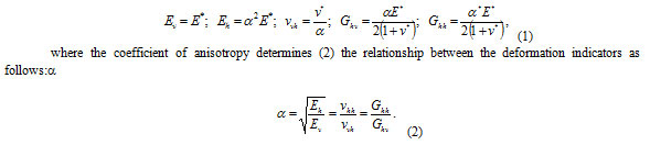
where Ev is the modulus of elasticity in the vertical direction (perpendicular to the plane of isotropy), Eh is the modulus of elasticity in the horizontal direction (plane of isotropy), vvh is the Poisson’s coefficient that characterizes the horizontal deformation caused by the longitudinal stresses, vhh is the Poisson’s coefficient that characterizes the horizontal deformation caused by horizontal stresses (stresses applied in the orthogonal direction); Ghv is the shear modulus in the vertical plane (perpendicular to the plane of isotropy); and Ghh is the shear modulus in the horizontal plane (plane of isotropy).
This coefficient is introduced in the model of Graham and Houlsby to establish the relationship between the elastic constants, which makes it possible to move from two elastic constants E* and v* to the elastic constants that are required for describing a transversely isotropic medium. The above five independent elastic constants and one dependent constant may be expressed as follows.
Nonlinear work of the rocks in the range between very insignificant to insignificant deformations is convenient to understand as the dependence (3) proposed by Hardin and Drnevich, which connects the tangent shear stress and shear strain:
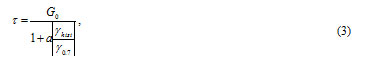
where G0 is the initial shear modulus in case of very insignificant strains; γhist – are shear deformations; γ0.7 is the boundary value of shear deformations; and a is the curve parameter.
When performing numerical simulations, it is necessary to convert the secant shear modulus in expression 5 into the tangent shear modulus (4):
![]()
Based on the assumption that the Poisson’s coefficient v does not change in the process of loading, the tangent modulus of volumetric compression (5) may be determined from the value of current loading of the tangent shear modulus:
![]()
The influence of the mean stress p on the ability of rock to resist deformation in case of deformation may be introduced via the exponential law (6):
![]()
where σ3 is the minimum main stress; c is cohesion; φ is the angle of internal friction.
The above expressions 1-6 make it possible to describe the nonlinear elastic behavior of an isotropic medium. According to the obtained formulas, each moment (value of deformation) may be easily matched with the value of the tangent shear modulus and the bulk modulus of compression. After transformation of the volumetric compression modulus and the shear modulus into the tangent modulus of elasticity and Poisson’s coefficient, and after substituting them into equation 11, with regard to equations 5-9, we will obtain the tangent flexibility matrix for a transversely isotropic medium.
During simulation, it is also necessary to consider the impact of rheology on the deformation properties of solid claystone-like clays. Work [29] shows that the long values of the deformation modulus, the coefficient of lateral deformation and the shear modulus may be determined through the following expression (7):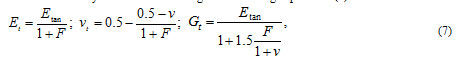
where F is the creep function; Et, vt, Gt are variables modules of deformation and shear, and the coefficient of transverse deformation, respectively.
The creep function Ft (8) in these formulas, except for the experimental determination, may be expressed with the use of the known constants β and δ (table 1):
![]()
Table 1: Values of the β and δ parameters obtained from the results of testing rock samples for creep under volumetric compression
| Parameter | Lateral pressure σ2= σ3, MPa | The average value | ||
| 0.2 | 0.6 | 1.0 | ||
| β | 0.891 | 0.898 | 0.863 | 0.884 |
| δ, 1/s | 0.013 | 0.0136 | 0.0086 | 0.0121 |
Development of a numerical model for predicting earth surface deformations on the example of the “Obvodny Kanal” deep-level subway station.
The “Obvodny Kanal” station of the Saint Petersburg subway is a pylon-type station; its building was completed in 2010. The station is located at the depth of 65 m from the surface in solid claystone-like clays. Thickness of solid clays over the roof of the station is 22 m, covered by quaternary alluviums represented by sandy loams, loams and water-saturated sands. The length of the station is 156 m. The station consists of three parallel tunnels of circular shape with the diameter of 9.5 m each. The tunnels are interconnected with 3.6 m wide openings. The escalator tunnel and the underground hall of the escalator tunnel join the subway station from the side of the station tunnel. The station was built with the use of the mining method with stage-wise opening sections of the tunnels in passes of 0.75 m. The lining of the tunnels was made of 0.4 m thick concrete tubular liners, with 1.15 m lagging behind the face crown. The moment of lining commissioning was the moment of grouting the space between the lining and the rock contour. Grouting was made into the fourth ring from the face. Face stability was ensured by the use of horizontal buntons. The elements of the station were built in a sequential manner. First, the first and second lateral station tunnels were built. After that, the Central station tunnel was build, followed by opening the inlets. The joint section of the escalator tunnel lobby and the auxiliary tunnels were built in the last turn.
The prediction of the earth surface deformations caused by building the “Obvodny Kanal” subway station was made according to the methods described in section 2.1. In the first stage, the numerical simulation was made to predict displacements of the rock contour of the station tunnels and the joint between the escalator tunnel and the station tunnels. In the second stage, the values of the tunnels rock contour deformations obtained in the first stage were applied as forced displacements to the contour of underground structures, which made it possible to predict propagation of deformation from the subway station to the surface. A geometric representation of spatial numerical model of the “Obvodny Kanal” station complex corresponding to the second stage is shown in Figure 1.
In performing the numerical simulation, the standard boundary conditions for the geomechanical tasks were adopted: displacements along the bottom face of the model are prohibited in the vertical direction, the top face of the model may freely deform, displacement on the lateral faces of the displacement model is prohibited in the directions perpendicular to these faces.
The vertical component of the initial stress state was determined using the gravitational law, and the horizontal component was determined with consideration of the lateral pressure coefficient. Since their formation, the considered claystone-like clays have undergone significant changes. These changes have been caused by both mechanical and chemical influence, and therefore their natural stress state cannot be determined using the existing methods. The back calculation performed by the authors showed that the value of the coefficient of lateral pressure was approximately in the range between 1.1 and 1.3. The mean value of this coefficient was adopted for numerical simulation.
In course of the numerical simulation of the subway station structures, the elastoplastic model based on the strength criteria of Coulomb and Mohr was adopted for the description of weak soils and clays in the transition layer. Solid claystone-like soils are described with the use of the model described in section 2.2. The physico-mechanical properties of weak soils and clays in the transition layer are summarized in Table 2, and those of the solid claystone-like clays – in Table 3. The indicators of solid claystone-like clays are listed with regard to their creep. The physical and mechanical properties of geological formations of the quaternary alluvium (soft ground) were determined as average weighted from the entire thickness of the quaternary alluviums. The test calculations showed that changes of the properties of quaternary alluviums within 25% had almost no effect on the final value of predicting earth surface deformations (the change was less than 1%). Thus, the assumption may be considered substantiated.
Table 2: The estimated mechanical properties of weak ground soils and clays in the transition layer
| Rock name | g kN/m³ | E0, MPa | v | c, kPa | j, deg |
| Weak soils | 20 | 12 | 0.3 | 15 | 20 |
| Clays in the transition layer | 21 | 60 | 0.4 | 100 | 22 |
Note: g is the specific weight of rocks; E0 is the modulus of deformation; v is the coefficient of transverse deformation; c is cohesion; and j is the angle of internal friction.
Table 3: The estimated mechanical properties of solid claystone-like clays
| Rock name | g kN/m³ | Eref, MPa | G0ref | Eur, MPa | v | m | a | a | g07 | c, kPa | j, deg |
| Solid claystone-like clays | 22 | 100 | 350 | 150 | 0.35 | 0.75 | 1.48 | 0.385 | 0.000035 | 150 | 23 |
Note: g is the specific weight of rocks; Eref is the modulus of rock deformation outside the range of insignificant deformations; G0ref is the rocks shear modulus outside the range of insignificant deformations; v is the coefficient of transverse deformation; m is an indicator of the effects of insignificant main stresses on the rocks deformation properties; a is the value of anisotropy of the deformation properties; a is the indicator of the shear modulus change curve in the range of very weak to weak deformations; g07 is the shear deformation that corresponds to the point of reducing the initial shear modulus by 30%; c is cohesion; and j is the angle of internal friction.
The local numerical model reflects only the part of the underground structures and rock mass that was necessary and sufficient for predicting rocks deformation in the vicinity of the considered structures. For example, for the purpose of predicting the shift of natural rock contour in the station tunnels, a 40 m long section of the station was considered, while the total length of the station was156 m. This allowed us to greatly reduce the size of the local model, and to increase detalization of numerical modeling of individual processes in building underground structures.
The global numerical model included the rock massif (Figure 1) with the size of 500×500×100 m, and the subway station itself. The model includes only the part of the station located in the solid clays, while the facilities in weak ground (the escalator tunnel, the vertical shaft) were not included into the model.
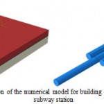 |
Figure 1: The geometric representation of the numerical model for building the structures of the “Obvodny Kanal” subway station
|
Results
The results of full-scale observations of earth surface deformations during building the «Obvodny Kanal” subway station
In the process of building the station, detailed monitoring of the earth surface deformation and settlement of buildings and structures was performed within the area of the underground works. The analysis of field monitoring of the earth surface settlement is presented for the period between 03.10.2007 and 22.12.2009.
The results of earth surface displacement after completion of the subway stations are shown in Figure 2. The dashed line is the design contour of the subway station and the adjacent auxiliary structures. Analysis of development of the earth surface settling was made in the characteristic reference points (Figure 3, the reference points are marked in blue on Figure 4). Reference point No. 15 is located above the central axis of the inclined tunnel. Reference point No. 31 is located in the vicinity of the vertical projection of the tension station to the surface, and the vestibule of the subway station. Reference point No. 40 is located over the left station tunnel beyond the openings. Reference point No. 46 is located between the central and the right station tunnel beyond the openings. The values of settlement obtained by these four reference points allowed us to assess the impact of building individual elements of the station complex on the settlement of the surface. Unfortunately, no measurement of the earth surface settlement has been performed over the area of the station where opening was performed. Reference point No. 26 located closest to the site of the tension station construction and to the junction between the approach opening and the underground hall of the station was excluded from the detailed analysis, since the data for this benchmark have been absent until the end of the subway station complex construction works. However, during building the isofields of surface settlement, reference point No. 26 was not excluded.
As of 03.10.2007, the magnitude of land settlement at the reference point No. 31 was 34 mm, reference point No. 40 – 57 mm, reference point No. 46 – 52 mm. The value of ground surface settlement at reference point No. 15 was close to zero. This allows us to say that the beginning of measurements corresponds to the initial stage of station construction, which includes building the central station tunnel and expanding the side tunnels of the station to the designed dimensions. According to the data obtained from reference points No. 40 and No. 46, the growth of the earth surface settlement was observed until 03.02.2009. The value of earth surface settlement by the end of the reporting period amounted to 72 mm for reference point No. 40, and to 66 mm for reference point No. 46, respectively. Further observations of the earth surface settlement at reference points No. 40 and No. 46 prove a reduction of the settlement development rate.
During the period between 17.04.2009 and 03.10.2007, an increase in the vertical displacement from 34 mm to 75 mm was observed at reference point No. 31. In the following period, until 11.12.2012, the increase of displacement was almost linear at a constant speed.
Considering the development of the earth surface settlement at reference point No. 15, it can be noted that for the period between 03.10.2007 and 20.11.2009, a smooth growth of vertical offsets was observed. It was caused by building station tunnels, making openings between station tunnels, construction of the tension stations and the joint of the approach working with the underground hall of the station. The value of settlement increased from 3 mm to 22 mm. Starting from 20.11.2009, the growth of the earth surface settlement accelerated, due to the start of building the inclined tunnel. 12.01.2011 may be considered as the end date of the development of soil settlement caused by the building of the inclined tunnel. During this period, the vertical settlement increased from 22 to 98 mm. Further observation showed that development of earth surface settlement decreased, and the growth of vertical displacements had almost stopped by then.
The obtained picture of the actual surface settlement allows saying that the maximum shift is observed above the joint between the escalator tunnel and the station tunnels. Above the center of the station, observation stations were absent, which did not allow to estimate the value of ground surface settlement under this site. However, the experience in the construction of other stations of the St. Petersburg subway in similar geological conditions shows that vertical settlement of the surface above the centre of the station may reach 70-80 mm, and 90 mm in some cases.
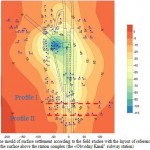 |
Figure 2: The mould of surface settlement according to the field studies with the layout of reference points on the surface above the station complex (the «Obvodny Kanal” subway station) |
 |
Figure 3: Development of surface settlement at reference points at various stages of building the station complex (the reference points layout is shown in Figure 2). |
The results of numerical modeling of the prediction of earth surface deformations in the building of the “Obvodny Kanal” subway station.
The mould of surface settlement above the “Obvodny Kanal” subway station with the layout of the deformation network is shown in Figure 4, and the diagrams of surface settlement along profiles I and II (see Figure 2) are shown in Figure 5. The value of 1 mm has been taken for building the mould of earth surface settlement at the border of the influence area.
Prediction of displacement of station tunnels contour performed on local models allowed us to obtain the following results. The value of radial displacements in the dome of the central station tunnel after completion was 96 mm, and in the side station tunnels this value was 78 and 84 mm, respectively. The ratio between the displacements in the soil and that in dome of station tunnels is approximately 0.5, in the sides and in the dome – 0.75, which correlates well with the results of field studies [1]. It should be noted that the maximum development of the radial displacements of tunnels contour was caused by the absence of face cross spacers. Additional displacement of the rock contour after commissioning of the lining was insignificant, and did not exceed 10 mm.
According to the results of the numerical simulation made on the basis of the developed global model, prediction of ground surface settlement was made, and the mould of surface settlement was built. The curve shows that the maximum settlement of the surface was concentrated above the joint of the escalator tunnel and the subway station. The value of surface settlement reaches 81 mm. In the end parts of the station, surface settlement does not exceed 60 mm. Qualitatively, the parameters of the settlement mould corresponds to the degree of influence from building the subway station, the width of the settlement mould is greater in the central part of the station and decreases toward the end parts of the station.
The results of the field studies and those of numerical modeling are compared in the next section.
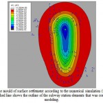 |
Figure 4: The mould of surface settlement according to the numerical simulation (the “Obvodny Kanal” subway station): the dashed line shows the outline of the subway station elements that was considered in the numerical modeling |
Discussion
The comparison of the values of surface settlement measured during monitoring and the predicted ones shows high repeatability. Thus, according to calculated profiles I and II (Figure 5), the difference between the maximum predicted and measured settlements did not exceed 4%, which is several millimeters in the absolute terms. Considering settlement at the remaining reference points, one can also see good repeatability, which in the whole confirms veracity of predicted earth surface deformations using the proposed method.
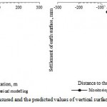 |
Figure 5: Comparison of the measured and the predicted values of vertical surface settlement along profiles I (a) and II (b) |
However, it should be noted that a number of reference points shows the discrepancy between the measured and the predicted values. The difference is observed in the area above the tension chamber and lateral junction of the tunnel to the underground hall of the station, where the predicted values approximately 3 times exceed the estimated values. Such significant deformations of the surface are caused by lateral junction of the inclined tunnel to the underground hall of the subway station. In case of such a junction, the tubular lining is removed, and a chamber of sufficient length (about 14 m) is built. The rock behind the lining is broken, which greatly affects the deformation of the rock circuit, significant zones of plastic deformation in the rock massif are formed in the vicinity of the chamber. Additional impact may cause deterioration of the technological regime of the structure of such joint between the inclined tunnel and the station hall. The same nature of earth surface deformations was observed in building other subway stations in St. Petersburg with lateral junction of inclined tunnels to the station hall. The difference in predicted and measured earth surface deformations is not explained by the effect of rock decompaction in certain construction area. In predicting deformations of the rock contour, the adopted geomechanical model of rock behavior did not take into account the possibility of rock decompaction. In addition, the influence of building the escalator tunnel on the value of the resulting earth surface deformation was not taken into account, which could also have some influence. The complex of the presented assumptions resulted in a significant error in predicting earth surface deformations above these areas, which should be corrected and taken into account in future modeling.
However, it should be noted in general that the proposed approach to modeling subway stations construction for the purpose of predicting earth surface deformations with regards to the existing geomechanical models of the solid claystone-like clays behavior allows to assess earth surface deformation above the areas of the station where significant rock decompaction is not expected as a result of construction works. Above the areas where such decompaction is expected, the presented approach provides poor prediction of expected values of the earth surface settlement. In order to improve the reliability of the predicting earth surface deformations above such areas, it is necessary to introduce changes to the geomechanical behavior model of solid claystone-like clays from section 2.2 in order to take into account rock decompaction with regards to the anisotropy of strength properties.
Conclusion
In conclusion, it can be noted that the proposed method of predicting earth surface deformations during the construction of subway stations or other complex spatial structures, based on coordination of the local and the global models, allows to obtain reliable results of ground surface settlement above the construction site. Such an approach, where prediction of earth surface deformations is separated from prediction of deformation of underground structures contour, allows to reduce the size of the global numerical model and at the same time to increase detalization of modeling the underground structures construction.
The performed approbation of the proposed method on the example of building the “Obvodny Kanal” subway station in St. Petersburg showed good general repeatability of the predicted and the measured values of settlement. At the same time, above the areas of the station, where construction of underground structures was accompanied by decompaction of the rocks of the enclosing massif, the predicted values of rock contour deformation do not match the real values. Thus, the proposed geomechanical model of solid claystone-like clays behavior should be modified to allow prediction of complex geomechanical processes, such as rock decompaction, and anisotropy of strength properties should be taken into account. However, if building underground structures is not accompanied by significant rock decompaction, the geomechanical model proposed in this article is sufficient for accurate prediction of deformations in the vicinity of the underground structure.
References
- Peck, R.B., 1969. Deep excavations and tunnelling in soft ground. Proceedings of the 7th ICSMFE, State-of-the-art Volume, Mexico City. Mexico: Sociedad Mexicana de Mecánica de Suelos, pp: 225-290.
- Limanov, Y.A., 1957. Collapsing the earth surface in tunneling in the Cambrian clays. Leningrad: The Leningrad Institute of Railway Engineers, pp: 239.
- Polakov, V.F., 1863. Studying the earth’s surface deformation along the Moscow-Petrograd track. Magazine Metrostroy, 3-4.
- Khutsky, V.P., 1999. Calculation of earth surface collapsing with time after building subway stations in St. Petersburg. Mining geodesy. Interuniversity collection of scientific works. The St. Petersburg State Mining Institute, pp: 39-42.
- Dolgikh, M.V., 1999. Movement of the earth surface during construction of subway underground facilities. Thesis of Candidate of Technical Sciences, St. Petersburg.
- O’Reilly, M.P. and B. New, 1982. Settlement above tunnels in the United Kingdom- their magnitude and prediction. Proceedings of the International Symposium Tunnelling‘82, London, 7-11 June. London: Institution of Mining and Metallurgy, pp: 173-181.
- Attewell, P.B., 1978. Ground movements caused by tunnelling in soil. Large ground movements and structures. London: Pentech Press, pp: 812-948.
- Mair, R.J., M.J. Gunn and M.P. O’Reilly, 1981. Ground movements around shallow tunnels in soft clay. Proceedings of the 10th ICSMFE, Vol. 1, Stockholm, 15-19 June. Rotterdam: Balkema, pp: 323-328.
- Selby, A.R., 1988. Surface Movements Caused by Tunnelling in Two-layer Soil. Nottingham: Eng. Geol. Of Underground Movements, pp: 71–7.
- Verruijt, A., 1997. A complex variable solution for a deforming circular tunnel in an elastic half-plane. International Journal for Numerical and Analytical Methods in Geomechanics 21: 77–89
- Sagaseta, C., 1987. Analysis of undrained soil deformation due to groundloss. Géotechnique, 37: 301–320.
- Rowe, R.K., K.J. Lo and G.J. Kack, 1983. A method of estimating surface settlement above tunnels constructed in soft clay. Canadian Geotechnical Journal, 20(1): 11-22.
- Loganathan, N. and H.G. Poulos, 1998. Analytical Prediction for Tunneling-Induced Ground Movement in Clays, Vol. 124, 9: 846-856.
- Volokhov, E.M., 2002. To the issue of assessing the influence of anisotropy of rocks on calculation of the stress-strain state of a massif in curse of tunneling. The methods of applied mathematics in transportation systems. Coll. of scientific works, issue 6.
- Sokolov, B.A., 1977. Anisotropy of clay soils with layered texture and oriented microstructure. In the book Soil science and engineering geology. Moscow: Editing House of the Moscow University, pp: 17-22.
- Bugrov, A.K. and A.I. Golubev, 1993. Anisotropic soils and foundations of structures. St Pertersburg: Nedra, pp: 245.
- Atkinson, J.H., 1975. Anisotropic elastic deformation in laboratory tests on undisturbed London clay. Geotechnique, Vol. 25, 2: 357-384.
- Graham, J. and G.T. Houlsby, 1983. Anisotropic elasticity of natural clay. Geotechnique, Vol. 33, 2: 165-180.
- Chang, C., P. Hicher, Z. Yin and L. Kong, 2009. Elastoplastic Model for Clay with Microstructural Consideration. J. Eng. Mech., 135(9): 917–931.
- Zhang, G, A. Germaine, J. Whittle and C.C. Ladd, 2004. Soil structure of a highly weathered old alluvium. Geotechnique, 54(7): 453-466.
- Pande, G.N. and K.G. Sharma, 1982. “Multi-laminate model of clays-a numerical evaluation of the influence of rotation of the principal stress axis.” Proceedings of the Symposium on Implementation of Computer Procedures and Stress-Strain Laws in Geotechnical Engineering, Eds., Desai, C.S. and S.K. Saxena. Acorn, Durham, N.C., pp: 575–590
- Wiltafsky, Ch., 2003. A multilaminate model for normally consolidated clay. Ph.D. thesis, Gruppe Geotechnik Graz, Graz University of Technology, Austria, Heft 18.
- Scharinger, F., H.F. Schweiger and V. Galavi, 2007. Multilaminate framework for modelling soil behaviour. Proceedings of the International Workshop on Constitutive Modelling – Development, Implementation, Evaluation and Application, Eds., Yin, Li, Yeung & Desai, Hong Kong, China, Hong Kong: Advanced Technovation Limited, pp: 65-74.
- Jardine, R.J., D.M. Potts, H.D. St. John and D.W. Hight, 1991. Some practical applications of a non-linear ground model. Proceedings of the 10th European Conference on Soil Mechanics and Foundation Engineering, Florence, Vol. 1, pp: 223-228.
- Protosenya, A.G., M.A. Karasev and N.A. Belyakov, 2015. Developing the numerical model for predicting the limit state of a massif with the use of the Stavrogin strength criterion. Physical and Technical Problems of Mining, 1: 3-11.
- Karasev, M.A., 2012. Developing a nonlinear elastic transversely isotropic model. Problems of geomechanics, geotechnology and mine surveying. Proceedings of the Mining Institute, 198: 202-206.
- Karasev, M.A., 2014. Forecasting sagging of the earth surface in building deep underground structures in the conditions of St. Petersburg. Problems of geomechanics, geotechnology and mine surveying. Proceedings of the Mining Institute, 204: 248-252.
- Hardin, B.O. and V.P. Drnevich, 1972. Shear modulus and damping in soils: Design equations and curves. Proc. ASCE: Journal of Soil Mechanics and Foundations Division, 98(SM7): 667-692.
- Bezrodny, K.P., S.N. Silvestrov and Y.M. Kartashov, 1982. Peculiarities of deformation of the Proterozoic clays. Magazine Metrostroy, 6.

This work is licensed under a Creative Commons Attribution 4.0 International License.


