Manuscript accepted on :
Published online on: 17-12-2015
Temperature Сontrol of the Battery for Hybrid or Electric Vehicle
Kirill Evgenievich Karpukhin1, Alexey Stanislavovich Terenchenko2, Alexander Alekseevich Shorin3, Sergey Vasilievich Bakhmutov4, Rinat Hanyafievich Kurmaev5
1Head of department, Doctor of philosophy. Federal State Unitary Enterprise Central Scientific Research Automobile and Automotive Institute "NAMI" (FSUE «NAMI»), Avtomotornaya Street, 2, Moscow, Russia, 125438. 2Director of Centre, Doctor of philosophy. Federal State Unitary Enterprise Central Scientific Research Automobile and Automotive Institute "NAMI" (FSUE «NAMI»), Avtomotornaya Street, 2, Moscow, Russia, 125438. 3Senior expert, Doctor of philosophy. Federal State Unitary Enterprise Central Scientific Research Automobile and Automotive Institute "NAMI" (FSUE «NAMI»), Avtomotornaya Street, 2, Moscow, Russia, 125438. 4Deputy CEO for Science, Doctor of science, professor. Federal State Unitary Enterprise Central Scientific Research Automobile and Automotive Institute "NAMI" (FSUE «NAMI»), Avtomotornaya Street, 2, Moscow, Russia, 125438. 5Head of department, Doctor of philosophy. Federal State Unitary Enterprise Central Scientific Research Automobile and Automotive Institute "NAMI" (FSUE «NAMI»), Avtomotornaya Street, 2, Moscow, Russia, 125438.
ABSTRACT: This paper covers negative impact of an accumulator temperature increase on an operational period of the battery during operation in an intensive current output mode. It suggests methods of heat emission calculation and application of an internal cooler in accumulator batteries. Analyzed the use of internal cooler, with the goal of providing high-quality thermal insulation of batteries to minimize communication with the external environment.
KEYWORDS: Electric vehicle; hybrid vehicle; accumulator battery; temperature control; heat emission; cooling; urban driving cycle
Download this article as:| Copy the following to cite this article: Karpukhin K. E, Terenchenko A. S, Shorin A. A, Bakhmutov S. V, Kurmaev R. H. Temperature Сontrol of the Battery for Hybrid or Electric Vehicle. Biosci Biotech Res Asia 2015;12(2) |
Introduction
Currently lithium batteries are the most common in vehicles with combined power units and in electromobiles, though their drawback is a negative impact of an accumulator temperature increase on an operational period of the battery during operation in an intensive current output mode. It is a common problem of all hybrid and electric vehicles. In hot external air temperatures during summer even usual city driving on a moderate speed causes heating of a lithium battery, and its temperature may exceed critical temperature, lying within 60 ÷ 70 0С. (Matthew A Keyser et al., 2003; Hossein Malekia et al., 1998; Shorin et al., 2013; Terenchenko et al., 2015).
In case of permanent overheat, an operational period of an accumulator battery decreases from 5-6 years to 2-3 years. (Kreyt and Blek, 1983; Zvonov et al., 2001; Slabosritsky et al., 2011; Slabosritsky et al., 2012, Slabosritsky et al., 2013).
To solve this problem accumulator batteries are equipped with cooling, air or fluid units. (Hendricks et al., 2010). The most popular are fluid units, due to their better heating capacity and heat conductivity, which makes them more effective than air ones.
When designing an accumulator battery cooling system, the question arises for what operating capacity this system should be designed. Apparently, it depends on the heating capacity of the accumulator battery’s operation during charging and discharging processes. (Pesaran, 2001; Kim Gi-Heon and Pesaran, 2006).
The main part
It is assumed that the heat emission capacity should be conducted the following way. The VAZ-1817 electromobile (Ellada) serves as an example.
In case of charging an accumulator battery in a stationary mode with direct current, the calculation is simple. It is a squared charging current, multiplied by total impedance of the battery. The result is the heat emission capacity.
Accumulator battery of the VAZ-1817 consists of 79 accumulator cells of WB-LYP90AHA type, the total impedance of a single accumulator is 0.0021 Ohm. The charging current of an on-board charging device is 12.5 A.
Heating capacity, emissioned in the accumulator battery is calculated according to the formula:
P = rac n (1)
where: I – charging current;
rac – accumulator cell total impedance;
n – number of accumulator cells in the battery.
Thus Р = 12.52 х 0.0021 х 79 = 26 W
Thus the heat emission capacity of the battery within this charging mode amounts to 26W. In case of charging from an external charging device, the acceptable charging current is 63A. In this case the heat emission capacity of the battery, calculated according to the (1) formula amounts to 660W.
On operational modes, i.e. motion modes of a vehicle, it is rational to calculate the heat emission energy using the mathematical simulation. The calculation should be based on the standard motion mode, for example, a testing cycle according to the UNECE Regulation # 83 “Uniform provisions concerning the approval of vehicles with regard to the emission of pollutants according to engine fuel requirements”.
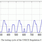
The testing cycle consists of urban and extra-urban driving cycles. The urban driving cycle consists of four equal stages, the duration of which is 195 sec; the stages should follow without pauses. The distance covered by a vehicle is 4.052 km, which results in the average speed that amounts to 18.7 km/h. The maximum speed is 50 km/h.
The end of the urban driving cycle tests is followed by the extra-urban driving cycle at a speed 120 km/h. This part of the cycle continues for 400 sec, and the covered distance is 6.955 km.
Figure 1 shows the testing cycle of the Regulation # 83.
 |
Figure 1: The testing cycle of the UNECE Regulation # 83 |
To perform calculation research of the mathematical simulation model of an electromobile the AVL CRUISE software package was used.
The AVL CRUISE software is designed for electromechanical systems simulation using methods of multimass systems dynamics and developed by the AVL Advanced Simulation Technologies Department.
The required information my be obtained by calculation research of the current value or squared current per cycle.
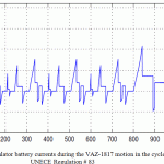
Figure 2 shows a current curve of the accumulator battery of the VAZ- 1817 in motion in the considered cycle.
 |
Figure 2 :The accumulator battery currents during the VAZ-1817 motion in the cycle, according to the UNECE Regulation # 83 |
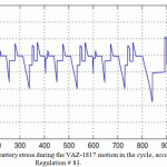
Figure 3 shows the stress curve of the accumulator battery during the VAZ- 1817 motion in the considered cycle.
 |
Figure 3: The accumulator battery stress during the VAZ-1817 motion in the cycle, according to the UNECE Regulation # 83 |
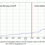
Figure 4 shows the curve of the squared accumulator battery current integral value, designed on the full cycle, according to the UNECE Regulation # 83.
 |
Figure 4: The curve of the squared accumulator battery current integral value on the full cycle, according to the UNECE Regulation # 83 |
The analysis of the curve of the squared accumulator battery current integral value on the full cycle, according to the UNECE Regulation # 83, built using the mathematical simulation (picture 4) allows to calculate heat losses in the accumulator battery both in the full cycle and in the urban and extra-urban driving cycles. These modes are given below.
Motion in the full cycle.
Calculation is made according to the following formula:
P=ΔI2/t racn,
where: ∆I2 – increment of the squared accumulator battery current integral on the considered section;
t –time duration of the considered section;
rac – accumulator cells total impedance;
n – number of the accumulator cells in the battery.
From the function on the Picture 4 we have: ∆I2 = 2.24 х 106; t = 1200 sec; rac = 0.0021 Ohm; n = 79.
Thus: Р = 310W.
It means that the heat emission in the considered operational mode of the accumulator battery is at the level of 310W.
Motion mode in the urban driving cycle
From the function on the Picture 4 we have: ∆I2 = 0.36 х 106; t = 800 sec; rac = 0.0021 Ohm; n = 79.
Thus: Р = 74.6W.
Motion mode in the extra-urban driving cycle
From the function on the Picture 4 we have: ∆I2 = 1.88 х 106; t = 400 sec; rac = 0.0021 Ohm; n = 79.
Thus: Р = 780W.
Choosing the cooler capacity according to the considered full cycle at the level of 310 W in the extra-urban cycle section results in the accumulator battery heating (Pesaran, 2001). The value of the accumulator battery temperature increase is calculated in the following way.
Specific heating capacity of the lithium-ionic accumulators amounts at (formula 3) c =1.1 kJ/kg*oC. In this case, the temperature increment is calculated according to the following formula:
ΔT = ΔP*t⁄ c*m
Where: ΔР – increment of the heating capacity, equal to the difference between the heating and cooling capacities,
ΔР = 780 W – 310 W = 470 Вт;
t – the extra-urban driving cycle duration, t = 400 sec.;
с – Specific heating capacity of the lithium-ionic accumulators;
m mass of the accumulators, m = 252,8 kg.
Thus: Δ Т = 0.68 0С.
Summary
Performing the similar calculation for the full cycle according to the UNECE Regulation No 83 indicates that even without a cooler the considered accumulator battery heats only by 1.33 0С. There is high probability that the obtained heating is compensated through the battery panels, the way it is done in the currently existing electromobiles (Bahmutov and Karpukhin, 2012). However, it must be considered that these electromobiles operate in above-zero temperatures, or in extremis in moderate below-zero temperatures. In Russia, however, the environment temperature may reach critical low temperatures. In this case, it is necessary to ensure proper thermoinsulation of accumulator batteries, minimizing contact of their internal content and environment (Terenchenko and Karpukhin, 2014). This aspect presumes the requirement for internal cooler implementation. Verification of the cooler’s characteristics is assumed to be performed according to the proposed methodology.
Acknowledgments
The paper was prepared under the agreement # 14.576.21.0031 with the Ministry of Education and Science of the Russian Federation (unique project identifier RFMEFI57614X0031) to create an experimental model of a hybrid electric vehicle with Range extender.
References
- Kreyt F., Blek U. (1983). Fundamentals of heat transfer. Russia: Moscow.
- Matthew A Keyser, Pesaran А. et all. (2003). Thermal Characterization of Advanced Lithium-ion Polymer Cells. Third Advanced Automotive Battery Conference.
- Hossein Malekia, Said Al Hallaja, J. Robert Selmana et all. (1998). Thermal Properties of Lithium-Ion Battery and Components. The Electrochemical Society.
- Pesaran А. (2001). Battery Thermal Management in EVs and HEVs: Issues and Solutions. First Annual Advanced Automotive Battery Conference, Las Vegas, Nevada: National Renewable Energy Laboratory. 1617 Cole Blvd. Golden, Colorado 80401.
- Zvonov V.A., Kozlov A.V., Kutenev V.F. (2001). Vehicle environmental performances in total life cycle. Moscow: NAMI.
- Kim Gi-Heon, Pesaran A. (2006). Battery Thermal Management System. Design Modeling EVS. Yokohama: Japan.
- Hendricks T.J., Krishnan S. et all. (2010). Enhancement of pool-boiling heat transfer using nanostructured surfaces on aluminum and cooper. International Journal of Heat and Mass Transfer, (53), (15-16). Р. 3357-3365.
- Bahmutov S.V., Karpukhin K.E., (2012). “Pure” cars: the directions of realization and reached results. Zhurnal avtomobil’nyh inzhenerov, 6 (77), (51-54).
- Terenchenko A.S. and Karpukhin K.E. (2014). Energy efficiency as a way of improving the environmental safety of vehicles. Transactions of NIZHNI NOVGOROD STATE TECHNICAL UNIVERSITY n.a. R.Y. Alekseev (2014). 4 (106), (299-305).
- Terenchenko, A.S., Karpukhin, K.E., Shorin, A.A., Sklyarinskiy, S.F. (2015). Optimizing the losses in a tractional induction motor within a hybrid system. Russian Engineering Research. Volume 35, Issue 3, (171-173).
- R.P. Slabosritsky, M.A. Khazhmuradov, V.P. Lukyanova. (2011). Analysis and calculation of battery cooling system. Radioelectronics and informatics, 3 (3-8).
- R.P. Slabosritsky, M.A. Khazhmuradov, V.P. Lukyanova. (2012). Studying of battery cooling system. Radioelectronics and informatics, 2 (5-8).
- A. Pesaran. (2001). Battery Thermal Management in EVs and HEVs: Issues and Solutions. National Renewable Energy Laboratory. 1617 Cole Blvd. Golden, Colorado 80401. Advanced Automotive Battery Conference. Las Vegas, Nevada.
- A. Shorin, K. Karpukhin, E. Zinovyev, S. Sklyarinsky (2013). Subject: Dynamic braking. Zhurnal avtomobil’nyh inzhenerov, 6 (83), (33-35).
- R.P. Slabosritsky, M.A. Khazhmuradov, V.P. Lukyanova; S.I. Prokhorets (2013). Using the analytical calculation method for cooling systems studying. Problems of atomic science and technology, 3 (85), (303-311).

This work is licensed under a Creative Commons Attribution 4.0 International License.


