

Manuscript accepted on :
Published online on: --
Dauren Kozhamkulov, Erbol Sarkynov, Tlektes Yespolov, Aleksandr Yakovlev and Katalin Zsuga
Kazakh National Agrarian University Kazakhstan, Almaty city, 050010, Abaia Avenue, 8
ABSTRACT: The study purpose is to substantiate the energy conservation technology of water lifting from watercourses and to conduct the theoretical and experimental studies of the water lifting technique using the hydro power of watercourses. The recently developed constructional and technological schemes of the pumping units of water hammer and suction-delivery types driven by the watercourse energy are presented, which in comparison with their analogues have the advantage of improving energy indicators. The results of the theoretical researches on the water hammer and suction-delivery techniques for water lifting from watercourses are provided, on the basis of which the major technological parameters such as total head, flow rate, pump power, and efficiency are determined, technical parameters are substantiated, and experimental models of pumping units are manufactured. The positive results of the experimental studies and tests are given.
KEYWORDS: Study; energy conservation technology; technical means of water lifting; water supply; agricultural consumers; watercourse energy; construction and technological scheme; water hammer pumping unit; suction-delivery pumping unit; technological and technical parameters; experimental model; test
Download this article as:| Copy the following to cite this article: Kozhamkulov D, Sarkynov E, Yespolov T, Yakovlev A, Zsuga K. Results of the Theoretical and Experimental Studies of the Water Lifting Technique Using the Hydropower of Watercourses. Biosci Biotech Res Asia 2015;12(2) |
Introduction
The article aims to address the problem of watercourse energy implementation within the system of agricultural water supply.
The most available and low cost type of water supply is the ground water sources, both natural and man-made, most of which can use the kinetic energy of the moving water as an energy source intended to drive the alternative pumping units working on the energy efficient and environmentally friendly water lifting technologies that improve mechanization of water supply for economic and domestic needs of the agricultural consumers [1,2].
Due to the absence of alternative pumping units in the market, the agricultural and other type consumers, located within the areas of watercourses, are forced to use the traditional centrifugal pumping units driven by the internal combustion engines requiring high operating expenses including expensive fuel.
The problem of the effective water supply with the use of the natural water energy resources is perspective and topical under the current conditions. It is rational to carry out its solution through the shallow watercourses with the implementation of pumping units and use of the water hammer and suction-delivery techniques for water lifting under certain conditions [3,4],the construction designs of which are technically simple and reliable in operation, and do not degrade the environmental ecology.
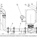 |
Figure 1: The constructional and technological schemeof a water hammer type pumping unit |
1 –air chamber,2 –waste valve, 3– pump body, 4 – delivery check valve, 5– delivery valve body, 6– sections of water supplying drive pipes, 7 –lower pipe elbow, 8 – upper pipe elbow, 9 –receptacle, 10–bottom shield, 11 – top shield, as well as fitting pipe connections: 14–nipple and 15 – clamp;and purchased items: 12–industrial 0.5 MPa pressure gauge, 13 –ball valve FB39330032700 (nominal diameter of 32 mm), 16 – hose pipe of 32 mm diameter,17 – clamp.
Study Method
The patent, theoretical, experimental, and preliminary-estimation methods are used in the paper.The authors developed two new construction and technological schemes of pumping units according to the provisional patent KZ No. 17789 of the water hammer (hydraulic ram) type (Figure1) and according to the provisional patent KZ No. 17787 of the suction-delivery type (Figure 2), which, if compared with the existing analogues, improve the energy indicators of pumping units and increase their range of use by the geodetic head.The hydraulic ram type pumping unit comprises the following major assemblies: air chamber 1, waste valve 2, pump body 3, delivery valve 4, delivery valve body 5, sections of water supplying drive pipes 6, lower pipe elbow 7,upper pipe elbow 8, receptacle 9, bottom shield 10,top shield 11, as well as fitting pipe connections: nipple 14 and clamp 15;and purchased items: industrial 0.5 MPa pressure gauge 12, ball valveFB39330032700 (nominal diameter of 32 mm) 13,and hose pipe of 32 mm diameter 16 with clamp 17.
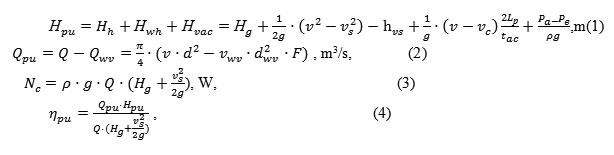
The suction-delivery type pumping unit comprises the following major assemblies: water-filled vessel 1, waste valve ready-assembled 2, pump body 3, delivery valve ready-assembled 4, connecting piece 5, sections of water supplying drive pipes 6, ejector 7, adapter sleeve 8, pump body of the transition pipe elbow 9, lower pipe elbow 10,and upper pipe elbow 11, receptacle 12, bottom shield 10,and top shield 11.
The operating principle of the water hammer type pumping unit is based on the implementation of the water hammer technique for water lifting, and operating principle of the suction-delivery type pumping unit is based on the joint use of the water hammer and suction techniques for water lifting. The novelty lies in the design of their receptacles, which are made in the form of a Z-shaped water supplying drive pipe with at elescopic joint intended for their adjustment according to the height of water intake and creation of an extra backwater effect inside the receptacle;as well as in the design of water waste valve having a counterbalance to the balanced axially adjusting load and to the hemispherical concave disc that is directed towards the water flow coming through the waste valve, which provides for the change (acceleration) of the actual closing time of the waste valve[5,6].Besides, the novelty of the suction-delivery type pumping unit consists in using a jet eject or according to the provisional patent KZ No. 17788 that generates vacuum inside the water supply system contributing to the increase in both water lifting height and water supply.
The water hammer type pumping unit (see Figure 1) comprises the following major assemblies: air chamber 1, waste valve 2, pump body 3, delivery valve 4, delivery valve body 5, sections of water supplying drive pipes 6, lower pipe elbow 7,upper pipe elbow 8, receptacle 9, bottom shield 10,top shield 11;as well as fitting pipe connections: nipple 14 and clamp 15;and purchased items: industrial 0.5 MPa pressure gauge 12, ball valve with nominal diameter of 32 mm 13,and hose pipe of 32 mm diameter 16 with clamp 17.
The suction-delivery type pumping unit comprises the following components: water-filled vessel 1, waste valve ready-assembled 2, pump body 3, delivery valve ready-assembled 4, connecting piece 5, sections of water supplying drive pipes 6, ejector 7, adapter sleeve 8, pump body of the transition pipe elbow 9, lower pipe elbow 10, and upper pipe elbow 11, receptacle 12, bottom shield 10, and top shield 11, ball valve with nominal diameter of 32 mm 13, and hose pipe of 32 mm diameter 16 with clamp 17.
Results of the theoretical studies of the water hammer and suction-delivery techniques for water lifting
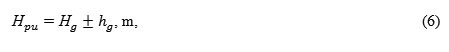
The studies were aimed at determining the analytical dependence between the input and output parameters of a pumping unit. On the basis of these studies, the major technological parameters, such as total head Hpu, flow rate Qpu, supplied power Npu,and efficiencyηpu were determined [1,2]:
whereНh, Нwh,Нvac,is the head, which is generated inside the pumping unit due to using geodetic pressure head and velocity head, water hammer and vacuum, m; Нg–geodetic pressure head, m; g –gravity factor, m/s2.
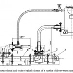 |
Figure 2: The constructional and technological scheme of a suction-delivery type pumping unit |
Water-filled vessel 1, waste valve ready-assembled 2, pump body 3, delivery valve ready-assembled 4, connecting piece 5, sections of water supplying drive pipes 6, ejector 7, adapter sleeve 8, pump body of the transition pipe elbow 9, lower pipe elbow 10, and upper pipe elbow 11, receptacle 12, bottom shield 10, and top shield 11, ball valve with nominal diameter of 32 mm 13, and hose pipe of 32 mm diameter 16 with clamp 17.
υ,υsis the water velocity in the water supplying drive pipe and its receptacle, m/s;
hvs is the head losses in the receptacle and water supplying drive pipe, m;
is thelength of the delivery pipe, m;
νcis the average water velocity in the delivery pipe at the waste valve closing (vc=f(tac) ), m/s; tacis the actual time of the waste valve closing (experimental data in the open pipes shows that tc=0.1 … 0.3s), s;
рa,рeare theair pressure and the gauge pressurein the ejector’s slot-type section, Pa;
Q, Qwv is the total water flow rate for the pumping unit and for the water discharge through a discharge hole of the waste valve seat, m3/s;
d, dwvare the inner diameters of the water supplying drive pipe and the waste valve seat’s hole, m;
F is the area usage factor for the waste valve seat’s flow section.
Experimental Procedure
The purpose of the experimental studies was the study of the technological process of water lifting from watercourses by means of water hammer and suction-delivery techniques, choice of rational options for the receptacle of a water supplying drive pipe and water waste valve, determination of the head losses and the local resistance coefficient in the waste valve, as well as the optimal length of the water supplying drive pipe, validation of the theoretical dependences, and determination of the basic pumping unit parameters.
The experimental studies on a specially prepared stand, which head was generated within the range of 0.5; 1.0; 1.5; 2.0; 5.0 m of water column, were carried out according to the developed constructional and technological scheme of a suction-delivery type pumping unit [7,8].
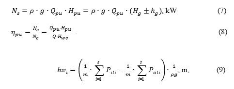
Parameters of the pumping unit were determined according to the experimental data obtained and using the following formulas.
Water flow rate for a pumping unit:
where vi is the volume of the supplied or discharged water per experiment, m3;
tmiis the measuring time of the supplied or discharged watervolume, s.
Head of a pumping unit:
where Hgis the pressure gauge reading in the delivery pipe, m;
hgis the height of the reference pressure gauge axis positioning relative to the delivery pipe axis, m.
Net power, efficiency, and head loss of a pumping unit:
where Hgis the pressure gauge reading in the delivery pipe, m;
hgis the height of the reference pressure gauge axis positioning relative to the delivery pipe axis, m.
Net power, efficiency, and head loss of a pumping unit:
whereυiis the water motion velocity inside the waste valve and inside the pump body, m/s;
g=9.81 m/s2 is the gravity factor;
diis the inner diameter of the waste valves eat’s hole and the pump body’s waste valve, m;
Fiis the area usage factor for the waste valve seat’s flow section and the pump body’s waste valve.
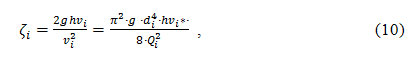
A test stand and experimental installation were designed and the required reference measuring and recording devices were prepared for the conduction of the experimental studies of a suction-delivery type pumping unit with a watercourse usage for the kinetic energy driving.
The stand was designed to simulate a watercourse with the water flow velocity up to 1.5 m/swith the open tray,and up to 5-10 m/swith the closed tray, water flow rate up to 0.01-0.05 m3/s,and ensured connection of the receptacle for a suction-delivery pumping unit to the watercourse[11,12].
The stand comprised a centrifugal pump 1 with flow rate up to 120 m3/h, supplying water tank 10 and suction water tank 12 with the capacity of 1…1.5 m3, the first of which is connected through the pipe 9 with the pump’s suction pipe 1,and between themselves they are interconnected through the pipe 11.
The stand has a special tray 6that is designed to simulate a watercourse, which through the pipe elbow 5, gate valve 3, and T-fitting 2 is connected with the pump’s delivery pipe 1. The T-fitting 2 is also connected through the gate valve 3 and pipe 4 with the water supplying tank 10.
The water supplying tray 6 is divided into two parts – an open one and a closed one. The closed part of the tray 6 in its upper part has a fitting, to which the pipe 7 is connected with the purpose of communication with the atmosphere and water head generating within small ranges (up to 3 m of water column), and the right side has a roof with a hole for a flange connection of the receptacle of a hydraulic ram type pumping unit 13.
The suction-delivery type pumping unit(Figure 3) 13 comprises a receptacle, delivery pipe with a waste valve, air chamber with the delivery check valve, which through the outlet fitting 14 together with the pressure gauge 15 and valve 17 are connected to the sleeve 16 supplying water to the receptacle 12 during the pumping unit operation.
 |
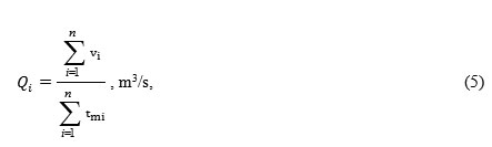
Figure 3: The scheme of the stand designed for testing the pumping units driven by the watercourse energy |
The stand has a special tray 6 that is designed to simulate a watercourse, which through the pipe elbow 5, gate valve 3, and T-fitting 2is connected with the pump’s delivery pipe 1. The T-fitting 2 is also connected through the gate valve 3 and pipe 4 with the water supplying tank 10.
The water supplying tray 6 is divided into two parts – an open one and a closed one. The closed part of the tray 6 in its upper part has a fitting, to which the pipe 7 is connected with the purpose of communication with the atmosphere and water head generating within small ranges (up to 3 m of water column), and the right side has a roof with a hole for a flange connection of the suction part of the hydraulic turbine 13 of the inlet strainer[13,14].
The hydraulic turbine type pumping unit 13 comprises the hydraulic turbine partwith the inlet strainer and acentrifugal pump, the discharge part 14 of which through the outlet fitting with a pressure gauge 18 and valve 17 are connected with the sleeve 16 supplying water to the receptacle 12 during the pumping unit operation.
The stand is equipped with the measuring devices: reference gauges 8, 15 and 18 intended to measure the pump head, and the impact-pressure tube 19 intended to measure the water exhaust velocity inside the watercourse.
The stand developed allowed under the laboratory conditions to verify conformity of the major parameters of the hydraulic turbine type pumping units to the technical specification, as well as to set the optimum mode of work and, if necessary, to clarify certain parameters.
Rational options for the basic assemblies of the pumping units have been experimentally selected:Z-shaped receptacle of the water supplying drive pipe with the telescopic connection and with the converging inlet strainer; the disk-shaped water waste valve with the hemispherical disk on a pivoted counterbalance and with the balanced axially adjusting load. The choice of a constructional and technological scheme of the delivery part was determined by testing the embodiments of the inlet strainer and expansion pipe with the assessment according to the criterion of the highest velocity (flow rate) inside the submerged pipe of the delivery part, and criterion of the highest head generated by a pumping unit.Out of the two tested variants of the divergent-convergentextension pipes, which are distinguished by the elbow-shaped inlet, the authors have chosen for the further studies that variant of the divergent-convergent extension pipe with an elbow-shaped inlet, which generates the velocity head increasing the total head of the pumping unit.The parameters of the pumping units were tested and refined, and the accuracy of the performed theoretical researches was confirmed. Coefficients of the local resistance were experimentally determined: waste valve – 2.27-4.86; extension pipe – 2.36-3.73; ejector – 0.30-0.73 and heads being generated by the pumping units: water hammer – 14.8-37.2 m; suction – 0.6-8.1 mat the inlet head of the watercourse – 0.5-10 m [15,16].
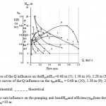 |
Figure 4: Q flow rate influence on the pumping unit headНpuand efficiencyηpufrom the flow rate Q at the length of the submerged pipeLsp=10 m. |
During the experimental studies of the technological process of the water hammer technique for water lifting, it was established that the head losses in the water supplying drive pipe mainly consisted of the local losses in the waste valve, which at the water course head Нwc=0.5…5 m and its water flow Qwv=0.007…0.020 m3/s comprised hv=0.6…2.7 m.
The studies showed that the water hammer head Нwhvalue mainly depends on the watercourse headНwc, as well as on the length of the water supplying drive pipeLpand frequency of the waste valve switching n, wherein the increase of these values contributes to the water hammer head increase. Thus, with the increase in the watercourse headНwc of 0.78 up to 5.33 m, the Нwh increases: of 15.7 mup to 35.3 mat theLp= 3.5 m; of 18.9 mup to 32 mat the Lp=5 m; of 14.8 mup to 37.2 mat theLp=7 m,and of 16.4 mup to 36.6 mat the Lp=10 m. Increase in the water hammer hear contributes to the growth of the waste valve switching frequency at its constant parameters: of 95.3 min-1up to 146 min-1atLp=3.5 m; of 65.3 min-1up to 127.8 min-1atLp=5 m; of 58.3 min-1up to 144 min-1atLp=7 m,and of 50.7 min-1up to 125.3 min-1atLp=10 m, wherein the switching frequency increases with the reduction in length of the water supplying drive pipe. The actual time of the waste valve closing is between 0.1 … 0.3 s, and the cycle time – 0.7 … 1 s. When assessing the technological process by the pumping unit flow rate, the optimum area of the water supplying drive pipe lies within the ranges of 5…8 m.
The results of studying the technological process of the water hammer technique for water lifting are shown in the graph (Figure 6), where the dependencesНpu, ηpu=f(Qpu) are given [1,2]. The studies have established that the working head of the pumping unitНpu (curves 1, 2, 3, 4,and 5),in the circumstance of the flow rate Qpu increase,is reduced at all operating modes, and the efficiencyηpu (6, 7, 8, 9,and 10) tends to increase with its optimum values for each operating mode. Thus, atLp=10 mwith an increase in the flow rateQpuup to 1.0 dm3/s,the working headНpu reduces from 10…20 m down to 4…6 m, and efficiencyηpu increases of 0.17…0.35 up to 0.6…0.8. The same is observed atLp= 7; 5; 3.5,and 2 m. The graph demonstrates the theoretical valuesНpu, ηpu=f(Qpu) for the operating mode atНwc=3.48 m, which discrepancy with the experimental data does not exceed 3-5%, which confirms the accuracy of the formulas (1), (2),and (4).
The results of the ejector study are shown in the graph (Figure 4), where the dependences Qvac =f(Нvac) are given. The studies have established that the ejector flow ratefor the air suction from the water-filled vessel was changing within the range of 0.7…30 dm3/sat the generated vacuum of 0.25…5 m. The best variant of the supplying ejector and generated vacuumis the ejector with an additional passive nozzle.
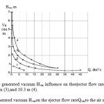 |
Figure 5: Influence of the generated vacuum Hvacon the ejector flow rateQvacto the air suction |
The results of studying the technological process of the suction-delivery technique for water lifting are shown in the graph (Figure 5), where the dependencesНpu, ηpu=f(Qpu) are given, including those compared with the water hammer technique for water lifting (Figure 5).The graph shows that thejoint use of the head pressure and vacuum contribute to the flow rate increase by 18…28% and to the efficiency increase at the low flow ratesby 8%, which confirms the effectiveness of vacuum usein a pumping unit(Figure 6)[17,18].
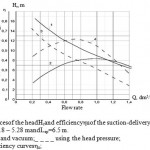 |
Figure 6: Comparative dependences of the headНrand efficiencyηuof the suction-delivery pumping unit on the flow rate Q at the watercourse headНwc = 5.18 – 5.28 mandLsp=6.5 m. |
Testing the experimental model of the suction-delivery type pumping unit driven by thewatercourse energy
The experimental model of the suction-delivery type pumping unit driven by the watercourse energy was manufacturedaccording to the developed working drawingsand technical documentationat the Temirtau Casting and Mechanical Pilot “TLMZ”, LLP (Talgar city, Kazakhstan) under the contract. The control over the manufacturing process and reception of the experimental models is carried out by the project executors in accordance with the delivery and acceptance certificate.
Testing of the experimental model was carried outon the test standin the laboratory and economic conditionsin compliance with the developed technique fortestingwith the measurement of the main indicators (flow rate, head, and efficiency).
The laboratory testing of the pumping unit consisted of two stages:
- Performance check of the main pumping unit’s assemblies: pump, receptacle,and retaining parts.
- Testing intended to determine the major parameters of the pumping unit: flow rate Q, generated head Нr,net power Np,and consumed power NНu,and efficiencyηНpuof the pumping unit.
In order to determine the major parameters of the pumping units,the following measurements were performed and their sequence (Figure 7).
The receptacle part of the pumping unit was immersed into the water course and connected to the water supplying drive pipe of the stand, which created watercourse.After the technological process of the pumping unit was stabilized, the following measurements were carried out in a 3-fold replication: volume of the water supplied through a water delivery sleeve of the pumping unitin to the measuring tarred vessel Viand time of measurement by a stop watch ti; the gauge pressure (head) in the discharge pipes of the pumping unitsНg according to the readings of the reference pressure gauge; the required water volume passing through the pump part into the tarred vesselVr and time of its filling by the stopwatch tr.Processing of the testing results according to the measurements obtained is carried out using the above mentioned formulas: (5, 6, 7, 8, and 9).
Below is the technical characteristic of the pumping unit.
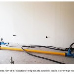 |
Figure 7: General view of the manufactured experimental modelof a suction-delivery type pumping unit. |
Technical characteristics of the suction-delivery type pumping unit:
Pumping unite type – portable, hydro turbine
Flow rate – 3.0…5 m3/h
Head – up to 10…15 m
Efficiency – 0.5…0.6
Water velocity with the watercourse – above 1.2…1.5 m/s
Water flow per drive – 0.01…0.04 m3/s
Watercourse head – above 0.5…1 m
Waste valve switching frequency – 30 min– 1
Strainer diameter – 200 mm
Inner pipe diameters: – of the water supplying drive pipe – 93.3 mm
– of the delivery pipe – 67.5 mm
Inner diameter of thewaste valve seat’s discharge hole – 78 mm
Waste valvestroke – 20 mm
Inner diameter of thedelivery valve seat’s discharge hole – 37 mm
Inner diameterof the water lifting pipe (sleeve) – 32 mm
Power: net – up to 0.2 kW, consumed power–up to 0.4 kW
Mass of the counterbalance loadfor thewaste valveswitching – 0.9…2.85 kg
Dimensions (length × width × height) – 10270×500×10 500 mm
Pumping unit weight – 60 kg (sleeve not included)
Service time – more than 7 years
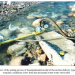 |
Figure 8: View of the testing process of the experimental model of the suction-delivery type of pumping unit in economic conditions (view from the ejector and water waste valve side). |
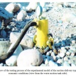 |
Figure 9: View of the testing process of the experimental model of the suction-delivery type of pumping unit in economic conditions (view from the water suction tank side). |
The results of the laboratory and economic testing of theexperimental model of the suction-delivery type of pumping unitare given in Table 1.
Table 1:The results of the laboratory and economic testing of the experimental model of the hydraulic ram type and suction-delivery type of pumping units
| Indicator | Marking
measurement unit |
Indicator value according to the TS | Indicator value according to the test |
| Flow rate of the pumping unit
Head of the pumping unit |
Qr, m3/h
Hr, m |
up to 5
up to 10 |
2…4.7
5…12 |
| Water flow per drive of the pumping unit
Watercourse head |
Qwc, m3/s
Нwc, m |
–
above 0.5…1 |
0.01…0.04
0.5…5 |
| Water velocity in the strainer
Watercourse debit |
u, m/s
D, m3/s |
1.2…1.5
0.01…0.05 |
0.7…1.5
0.02…0.025 |
| Pump power: net
consumed |
Np, kW
NН, kW |
0.2
0.4 |
0.15…0.24
0.3…0.4 |
| Efficiency of the pumping unit | hpu | above 0.5 | 0.34…0.6 |
| Waste valve switching frequency | n, min-1 | 30 | 30…90 |
The laboratory and economic testing of the experimental model of the suction-delivery type of pumping unit are carried out with the positive results, the major parameters of which comprised as follows: flow rate–2.0-3.7 m3/h, head – 5-12 m,and efficiency– 0.34-0.6. The parameters obtained correspond to the technical specification requirements and are the basis for its implementation into the pasture water supply system used by the agricultural consumers within the agro-industrial complex of Kazakhstan [19, 20].
Based on the studies performed,the authors developed and manufactured the experimental models(Figures 8,9)pf a water hammer and suction deliver type pumping units, which were consistent with the TS and working drawings. According to the TS and working drawings,the laboratory and economic tests were carried outwith the positive results, the major parameters of which comprised: flow rate of the pumping units –3…5 m3/h, head–10…17 m, watercourse flow per drive– 0.01…0.04 m3/s, inlet water head to the receptacle– 0.5…5.0 m, efficiency of the pumping units – 0.5…0.55.
Conclusion
- According to the results of the studies performed, the newconstructional and technological schemes are developed for the water hammer and suction-delivery type pumping units, which feature the novelty – are protected by the threeprovisional patents КZ for the invention.
- The theoretical and experimental studies are carried out, the experimental models are developed and manufactured for the water hammer and suction-delivery type pumping units, and the tests are conducted that have positive results and confirm accuracy of the theoretical assumptions.
- The study results can be recommended for the practical implementation.
References
- Sarkynov, E. (2013).Substantiation and development of the energy conservation technologies and technical means for water lifting using the hydropower for the watercourses hydro-energy drive.Report on the research work (intermediate),state registration number No. 0112 RK00178. Almaty:KZNAU.
- Smoliar,V., Burov,B., Makhmutov, T., and Kasymbekov,D.(2002).Water Resources of Kazakhstan (surface and underground waters, the current state).Reference book.Almaty: SRCGylym.
- Kaplan,R., &Yakovlev,A.(1986).Mechanization of water supply in pastures.Alma-Ata: Kainar.
- Usakovskiy,V.(2002).Water supply and drainage in agriculture.Moscow: Kolos.
- Yakovlev,A., Nesterov,E., and Sarkynov,E.(2004).Mechanization of water supply for the agricultural enterprises within the agro-industrial complexunder the market conditions.Bulletin of Agricultural Science of Kazakhstan, Almaty, 12, 61-62.
- Knight, U. (2001). The ‘Black Start’ situation.Section 7.5. In Power Systems in Emergencies: From Contingency Planning to Crisis Management. John Wiley & Sons.
- Bohnet, A., Giese, E., &Zeng, G. (1999). DieautonomeRegionXinjiang (VRChina).EineordnungspolitischeStudie.Schriften 72. Munster, Hamburg, London:LitVerlag,band 72. ISBN 3-8258-2971 5.
- Giese, E., Sehring, J., Trouchint, A. (2004).ZwischensttaatlicheWassernutzungskonfliktein. Diskussion Papers, 18.
- Starodubtsev, V. (2007). Degradation Processes in Deltas of the Rivers with Flow Regulation. Basin Water Management.International Congress on River Basin Management, Turkey, Antaliya,828-843. Retrieved May 15, 2015, from www.dsi.gov.tr/english/congress2007/chapter_2/pdf.
- Hamududu, B., &Killingtvelt, A. (2012, February). Assessing Climate Change Impacts on Global Hydropower.Energies,5, 305-322.
- Raichle, B., Sinclair, R., & Ferrell, J. (2012).Design and Construction of a Direct Hydro Powered Coffee Depulper.Energy for Sustainable Development, 16, 401-405.
- Davis, R. (1999).Water Power in the Andes.Yesterday’s Solution for Today’s Needs.
- Reynolds, T. (1983).Stronger than a Hundred Men: A History of the Vertical Water Wheel (Johns Hopkins Studies in the History of Technology) (pp.106, 306-307, 342-349).
- Pumping unitANS-60D (p. 3). (1990). Moscow: Vneshtorgizdat.
- Pumping unitAN-2K9-M1 (p. 3). (1988). Moscow: Vneshtorgizd at.
- Yakovlev, A., and Sarkynov, E. (2002,September 15). Suction-Delivery Type Pumping Unit.Provisional patent 17787 KZ,bulletin 9.
- Yakovlev, A., and Sarkynov, E. (2006, September 15). Ejector.Provisional patent 17788 KZ,bulletin 9.
- Yakovlev, A., and Sarkynov, E. (2006, September 15). Hydraulic Ram Type Pumping Unit.Provisional patent 17789 KZ,bulletin 9.
- akovlev,A., Sarkynov,E., Asanbekov,B., and Birimkulova,B.(2011).Study of the water hammer type technique for water lifting from watercourses.Study, results,2 (050), 46-149.Almaty: KZNAU.
- Yakovlev, A., and Sarkynov, E.(2005).Implementation of the water hammer effect in the pumping unitfor water lifting from watercourses.KZNTU Herald,Almaty, 4, 53-57.

This work is licensed under a Creative Commons Attribution 4.0 International License.


