

Manuscript accepted on :
Published online on: 19-12-2015
Detecting the Drowsiness Using Eeg Based Power Spectrum Analysis
S. Rajkiran*, R. Ragul and M. R Ebenezar Jebarani
Sathyabama University
ABSTRACT: Detection of drowsiness is one of the biggest challenges for human beings. Especially during the night driving, it is very important for the person to be in awakening state. While driving, a matter of few seconds of the involuntary activity of humans may end in an accident. In order to detect the drowsiness the mind wave mobile, along with the Brain-Computer Interface (BCI) technology is used in this proposed work. Millions of neurons play a major role in the human brain. During every movement of the human beings, the pattern of neuron changes while walking, running, sleeping mode etc. The special device of mind wave mobile helps to detect the blink rate and meditation period through variations occur in the eye movement. The Level Splitter Section (LSS) plays a vital role in analyzing both meditation and blink rate in order to control the speed of the vehicle. The main idea of the proposed work is helping the person to reach the destination point in a safe manner.
KEYWORDS: Brain-Computer Interface (BCI); Level Splitter Section (LSS); Brainwave Module; Electroencephalogram (EEG) signals
Download this article as:| Copy the following to cite this article: Rajkiran S, Ragul R, Jebarani M. R. E. Detecting the Drowsiness Using Eeg Based Power Spectrum Analysis. Biosci Biotech Res Asia 2015;12(2) |
Introduction
The main aim of this work is to control the device, based on the electrical signals of the brain. The Brain-Computer Interface system is a type of a communication system, which helps the people in controlling the various computer based applications using the thoughts of human beings. The Electroencephalogram (EEG) helps to detect various changes occurs in the brain and sample the values in the normal state. Once the changes occur in the normal stage, then it intimates the BCI to perform the preprocessing functions and extracting the data. The accuracy level should be set during the initial stage itself.
The main objective of proposed work is:
- To detect the eye drowsiness with eyes open using Brain waves.
- To analyze the mental activities using Electroencephalogram with the help of the Brain-Computing Interface to reduce the speed of the vehicle.
In the earlier stages the technology monitors only the physical process of the brain that corresponds with certain forms [1]. Later it focuses mainly about detecting the facial expressions which occurs during the different stages of drowsiness [2]. After introducing of the wireless technology helped paralyzed patients to control the electric wheelchair [3]. Then it is developed for real time applications in detecting fusions of driver minds and driving data information [4]. The emotions of human beings were controlled by playing their favorite music to control their hypertension [5]. With the advancement of the technology started to analyze the eye activity, deviation in the driver’s head and heart beat rate [6]. Used the infrared camera is to capture the driver’s face image for data validation [7]. The machine learning based approach is used to distinguish between the awake and drowsy states [8]. In the next stage attempted to scan the various emotions of the human by using the frontal midline theta and an alpha relation ratio [9]. In the recent stages the Image processing technique is used to monitor the driver’s facial expression and movement of the eye [10]. The major drawback in all these studies are failure in the warning signal, low accuracy, EEG signals doesn’t remain stable under the drowsy condition. To overcome all these drawbacks the proposed system is designed in such a way to detect the drowsiness even when the eyes are open.
Materials and Methods
Hardware and software used are
Hardware
- ARM lpc 2148
- Brainwave sensor
- LCD display
- RF transmitter
Software
- Compiler (KEIL IDE)
- Or cad design
- Programmer (Flash magic)
- Languages: Embedded C
Block Diagram of Proposed Work
The special technique of Brain-Computing Interface (BCI) is mainly used to interface both the external and internal device. The electrode which helps to takes the readings of both the attention and blink level.
The block diagram mainly consists of three different sections. They are
- Brain-Computer Interface
- Data Processing Section
- Vehicle Section
The Fig 1 describes about the Brain-Computer Interface (BCI) section. In the Brain-Computer Interface, the mind wave module scans the neural pattern for each and every second. The neural pattern varies during the various metabolic activities of human beings. The sensor region includes three different part, they are an EEG power spectrum, ground connection and the dry electrode unit. The dry electrode unit is responsible to sense the brain waves. Electroencephalogram is a method used in measuring the electrical activity of the brain. The sensor collects the raw brain wave signals and transmits the data to the next section which is called as the data processing section. Since the processing section cannot able to read the raw data as directly so it should be transferred in the form of packets.
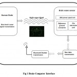 |
Figure1: Brain-Computer Interface |
The data which is sent from the Brain-Computer Interface section is received in the Data processing section. The data can be received by using the Bluetooth reception unit. The Fig 2 describes detail about the data processing unit. Then the received data is sent to the next section of Level Splitter Section (LSS) which is mainly responsible for splitting the values are received from the brain wave signal. Among all these three sections the Data Processing section is considered as the Heart of the process. The main function of the LSS section is to extracting the necessary data and conversion of raw data into the voltage value occurs in this unit. These extracted data are allowed to send through the vehicle section by using the serial data transmission technique. This serial data transmission is used to link both the data processing section and the vehicle section.
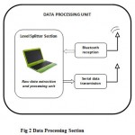 |
Figure 2: Data Processing Section |
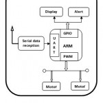 |
Figure 3: Vehicle Section |
The data which are sent from the data processing unit is received at the vehicle section. The Fig 3 explains about the vehicle section. The serial data is transmitted from the processing section which is allowed to receive at the vehicle section by using the serial data reception. Then the received data is sent to the next section of Universal Asynchronous Receiver Transmitter section (UART). The UART is a circuit which helps in the process of serial communication. The main use of UART is to form junction with RS-232, RS-422. These are all mounted in the hardware chip. The received data is sent to the next section of Pulse Width Modulation (PWM) is mainly involved in the process of controlling the speed of the motor so that it can able to reduce the speed of the vehicle. The General Purpose Input Output (GPIO) is also an integrated circuit which is mounted in the ARM controller. The main advantage of the GPIO is it can be controlled by the user even at the run time. All these three sections run in the simultaneous process to control the speed of the vehicle.
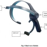 |
Figure 4: Mind wave Module |
The Fig 4 describes about the hardware kit of the Mind wave module. The device consists of Battery, Ear clip, Brain sensor and TGAM module. The device should be placed perfectly then only it can able to detect the brain signals in an efficient manner.
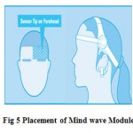 |
Figure 5: Placement of Mind wave Module |
The Fig 5 explains about the placement of the mind wave module. The dry electrode should touch the Forehead to capture the brain signals without any interruption. The ear clip must be positioned at the bottom of the ear which helps to place the device in the correct position.
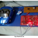 |
Figure 6: Hardware kit |
The Fig 6 explains about the hardware kit it consists of the toy car, ARM microcontroller. The kit is connected to the laptop. While running the coding the data from the laptop is transferred to the kit by means of USB to serial port convertor.
The brain wave signal is detected by using the Brainwave module and it captures the neural changes of the brain during the different activities of the brain. The raw data of the signals can be converted into the packets to transfer through the RF transmitter. During this process the coding used to collect the data sent by the brain wave module convert that into a voltage values. The threshold value should be set for both the meditation and blink rate value. Once the value goes beyond the threshold value the speed of the vehicle gets reduced. The meditation and blink rate values will vary for different persons.
Results and Discussions
In this proposed work the brainwave sensor is used to detect only the Alpha wave. The Alpha wave is generated during the eyes open and close state. The neural pattern changes according to the variations occur in the alpha waves.
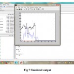 |
Figure 7: Simulated output |
The graph will be generated for the Meditation and Blink rate values. The Fig 7 explains that when the coding is allowed to RUN at the initial stage the coding will check for the proper connection of the external device. Then it starts plotting the graph based on the Meditation and Blink rate values.
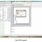 |
Figure 8: STOP command |
For each and every second the blink rate and meditation value will change and it will vary from person to person. The Fig 8 explains that once the blink and meditation level exceeds the threshold value the new command box opens as STOP and then it starts reduce in the speed of the vehicle. When the driver awakes then the vehicle continues to run in the same speed.
The main advantage of the proposed work is it can be able to detect the drowsiness with eyes open in an efficient manner.
Conclusions
Many attempts were given by the people to detect the drowsiness such as Image processing technique, facial expressions all that were ineffective because of failure in giving alert to the drivers, failure in the buzzers, detecting the eye movement. Since this proposed work is based on detecting the drowsiness level at the initial stages itself by scanning the neural patterns using the Brain-Computer Interface (BCI) technique it is most successful in detecting the drowsiness even with the eyes open state. In future, the Mind wave module can be modified to increase its accuracy state and new algorithm can also be designed.
References
- Anton Nijholt. Brain-Computer Interfacing for Intelligent Systems. University of Twenty Desney Tan, Microsoft Research
- G, Hernandez.N, Bergasa L.M, Parra, Yebes.J.J , Gavilan.M,Quintero. R, Llorca D.F, Sotelo.M.A. Drowsiness monitoring based on driver and driving data fusion Department of Electronics University of Alcal´aMadrid, Spain 2011 14th International IEEE Conference on Intelligent Transportation Systems Washington, DC, USA 2011.
- Esra Vural, Marian Bartlett, Gwen Littlewort, Mujdat Cetin, Aytul Ercil, Javier Movellan. Discrimination of Moderate and Acute Drowsiness Based on Spontaneous Facial Expressions. Institute of Neural Computation University of California San Diego, San Diego, USA 2010.
- Jzau-Sheng Lin and Win-Ching Yang. Wireless Brain Computer Interface for Electric Wheel Chairs with EEG and Eye Blinking Signals. International Journal Of Innovative Computing, Information and Control 2010.
- Kevin C. Tseng D Member IEEE Product Design and Development Laboratory Department. Emotion Recognition of EEG Underlying Favourite Music by Support Vector Machine of Industrial Design. College of ManagementChang Gung University Taoyuan, Taiwan 2012.
- Liang Wei. Multi-Source Information Fusion for Drowsy Driving Detection Based on Wireless Sensor Networks. School of Computer science and Engineering, Changshu Institute of Technology Changshu 215500, China 2013.
- M, Mousa K. Wali, Badlishah Ahmmad.R, and Subbulakshmi Murugappan. Subtractive Fuzzy Classifier Based Driver Drowsiness Levels Classification Using EEG.International conference on Communication and Signal Processing,India 2013.
- Shaoda Yu, Peng Li, Honghuang Lin, Ehsan Rohani, Gwan Choi, Botang Shao, Qian Wang. Support Vector Machine Based Detection of Drowsiness Using Minimum EEG Features. Dept. of Electrical and Computer Engineering Texas 2013.
- Singh Himani Parmar, Mehul Jajal,Yadav Priyanka Brijbhan. Drowsy Driver Warning System Using Image Processing by Electronics & Communication, GEC, Bharuch, Gujarat 2011.
- Upadhyay.R. Kankar, Padhy.P.K and Gupta.V.K. Classification of Drowsy and controlled EEG signals. Nirma University, International conference on Engineering, Delhi 2012.

This work is licensed under a Creative Commons Attribution 4.0 International License.


