

Manuscript accepted on :
Published online on: 24-12-2015
Vadim Igorevich Bespalov, Oksana Sergeevna Gurova, Natalia Sergeevna Samarskaya and Natalya Vladimirovna Yudina
Rostov State University of Civil Engineering (RGSU), Rostov-on-Don, Sotsialisticheskaya, 162, 344022, Russia.
ABSTRACT: In the article the authors give an attempt to evaluate the assessment of ecological efficiency and energy efficiency of one of the most promising technologies of realization of the construction industry enterprises' emissions cleaning process via hydrodynamic method with the use of foam which in the active zone of cleaning process realization can have either the foamy aerosol form (discrete bubbles), or a foam layer (where bubbles are located closely to each other and share common liquid film sides). Thus, the authors analyze physical essence of hydrodynamic method of ventilating air purification exhaust gases from polluting substances (toxic components) using the foam method with foam layer application or foamy aerosol and as a result receive parametrical dependences for the energy efficiency parameter and efficiency of air purification process in case of each method application. The authors present the results of the carried-out calculations graphically.
KEYWORDS: construction industry enterprises; purification of wasted and exhaust gases; ecological efficiency and energy efficiency of ways and means of emissions cleaning; toxic components
Download this article as:| Copy the following to cite this article: Bespalov V. I, Gurova O. S, Samarskaya N. S, Yudina N. V. Assessment of Ecological Efficiency and Energy Efficiency of Foam Use at the Construction Industry Enterprises by Emissions Cleaning Process. Biosci Biotech Res Asia 2015;12(2) |
Introduction
In modern conditions of an urbanization with the current structure of functional zoning of the cities there is a tendency to development of residential areas zone which is reflected first of all by the growth of office and business centers, commercial and public organizations, as well as other institutions of the nonproduction sphere (Kazuhiro Yuki, 2013, Marc Antrop, 2004, Paul Waley, 2009, Qingsong Wang et al, 2013, Vavilova, 2009). In contrast to such institutions industrial enterprises are concentrated close to city outskirts or a few kilometers away from the city in the industrial zone specially arranged for them. Only construction industry enterprises as well as construction sites remain in urban areas that can be advantageous and disadvantageous at the same time. (Ann T.W. Yu et al., 2014, Sukko Kim, 2005).
The expediency of placement of the construction industry enterprises in city building and large settlements areas is caused by a number of reasons. The main of them are: (Bespalov V.I., 2014). First, the construction enterprises need to be placed in areas available to the production consumers. Those areas are to have all necessary convenient transport communications, high level of workers service. Remoteness of the enterprises from such areas causes significant increase of capital and operational expenditures. Second, communication with life support systems, for example, with objects of water supply, sewerage, power supply and other engineering constructions and communications has to be provided. Third, reserve of productive forces, which is available generally in large cities and settlements that in turn will facilitate completing, moving and household arrangement of workers has to be provided. Thus, placement of the construction enterprises in the territory of the cities and large settlements promotes increase of labor productivity and decrease in production costs.
However the enterprises of the construction industry make negative impact (acoustic, vibration, thermal, chemical) on city environment, thus primary impact has chemical pollution of air environment (Bespalov V.I., 2014). More than 4 million tons of the polluting substances containing 85 polluting dust components, including 2,4 million tons or 58% of solid inorganic dust which represents the smallest firm particles are released into atmosphere by the construction enterprises annually. Those toxic components produce negative impact on infrastructural objects of the city and its population.
The processes of crushing, grind, pro-sowing, sawing up, and other movements of bulks are most often connected with formation of dust in conditions of production. In technological processes of construction actions connected with crushing and sorting stone, loading and unloading cement, lime, plaster, sifting sand and slag, etc. a significant amount of dust is allocated. The smallest particles of mineral dust are capable to be airborne as suspension for a long time in a working zone thus may get in workers’ breathing ways. The most widespread source of dust formation and spreading at the majority of enterprises is the bulk overload knot from conveyor to conveyor or from conveyor to the other technical equipment. Some of the main types of raw materials are crushed stone of various fractions and sand. As a result dust formation and release occurs due to mechanical interaction of technological raw materials particles (crushed stone, sand) among themselves, as well as their interaction with equipment surfaces.
In practice of urban environmental protection it is necessary to calculate, project and design engineering systems aimed to decrease the air environmental pollution. These systems generally include five basic functional elements at construction industry enterprises (Bespalov V.I., Gurova O.S., 2012):
- concentrating the polluting substances (toxic components) in their formation source zone with the main stream (volume) of technological raw materials;
- detention the polluting substances (toxic components) in their allocation zone source to the air in close proximity to the main stream (volume) of technological raw materials;
- catching the polluting substances (toxic components) in close proximity of the source of their emission to the atmosphere;
- purification of ventilating air and flue gases of the polluting substances (toxic components) just before their emission to the atmosphere;
- dispersion the polluting substances (toxic components) in a ground layer of the atmosphere directly after emission.
The most significant functional element for ensuring ecological safety of urban areas air environment from the listed ones is the element of purification of ventilating air and flue gases from the polluting substances (PS).
Questions connected with a choice of optimal technology (method-way-kind) (Bespalov V.I., 2005) and calculation of the corresponding technological parameters of realization of process of purification ventilating air and flue gases from the polluting substances (toxic components) for the construction industry enterprises are to be studied properly. Theory and practice of cleaning process realization are in constant development, new methods and ways of cleaning, new devices designs and original machines are being invented. However the most effective and very promising technology of cleaning process realization is the application of hydrodynamic method of cleaning with foam when as influencing the polluting substances (toxic components) use disperse system in the form of foam which in an active zone of realization of process of cleaning can be either in a form of foamy aerosol (discrete bubbles), or foam layer (bubbles are located closely to each other and have the common liquid film surfaces).
Methodology
Methods of research are based on general views of the theory of disperse systems, the system analysis and theory of systems modeling, analytical generalization of known scientific and practical results, methods of probability theory and mathematical statistics, expert opinions and other methods.
Results and Discussion
For assessment of ecological efficiency and energy efficiency of application of the hydrodynamic method of purification of ventilating air and flue gases from the polluting substances (toxic components) in foamy way with application of a foam layer when receiving foam on mesh, or the bubbling method we will consider physical essence of processes. The physical essence of the hydrodynamic method is realized in purposeful impact of the particles of toxic components to the cleaning active zone, in advance prepared in parameters of “external” disperse system presented by a foam layer possessing the moistening properties providing disperse phase division (particles of the polluting substance) and ventilating air (the main stream of flue gases) with the subsequent emission of the cleared air (the cleared gases) in the atmosphere.
Technological scheme of realization of the hydrodynamic method of cleaning with a foamy way with application of a foam layer when receiving foam on a mesh is submitted in figure 1.
The main principle of the technological scheme (figure 1) goes as follows. The polluted air stream (transitional T-II.1 system) enters the active cleaning zone 7. Water from the main economic water supply system 1 via the electromagnetic valve 2 comes to the working liquid reservoir 4 where water level is maintained automatically by means of ALR 3. From the reservoir 4, water is pumped to the mixer 10. At the same time foam from the foaming agent storage 6 moves to the foaming agent batcher 9, and then – to the mixer 10. The batcher 9 provides the demanded consumption of foam, and the mixer 10 provides the set concentration of foam solution. By means of pumping plant 13 ready foam solution is moved to the mesh foam generator 12. The external air moves to the mesh foam generator 12 by means of the fan 11 via the air intake 15. As a result the foam stream with the advanced moistening properties from the mesh foam generator 12 directly accesses the cleaning active zone 7, forming filter-bed which stability is provided with the reinforced site 14 and which moistens PS particles, collecting them from the air stream and providing air cleaning. The air stream (transitional T-II.2 system) leaves the active cleaning zone after purification process. In order to avoid foam missing from the cleaning active zone 7 the foam collector 16 is set. The formed sludge is directed to drainage. For the foaming agent batcher 9, mixer 10, fan 11 and pumping plant 13 service LRR 5 is provided. To provide the control of pressure of foam solution in front of the mesh foam generator 12 the manometer 8 is installed.
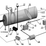 |
Figure 1: The technological scheme of realization of process of ventilating air (flue gases) purification in a foamy way when receiving foam in mesh foam generators |
1-main economic water supply system; 2-electromagnetic valve; 3-average level regulator (ALR); 4-working liquid reservoir; 5-locking regulating reinforcement; 6-foaming agent storage; 7-active cleaning zone; 8-manometer; 9- foaming agent batcher; 10-mixer; 11-fan; 12-mesh foam generator; 13-pumping plant; 14-reinforced site of cleaning active zone; 15-air intake; 16-foam collector
The technological scheme of realization of the hydrodynamic method of cleaning in a foamy way with application of a foam layer when receiving foam bubbling is submitted in figure 2.
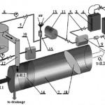 |
Figure 2: The technological scheme of realization of process of ventilating air (flue gases) purification in a foamy way when receiving foam bubbling |
1-main economic water supply system; 2-electromagnetic valve; 3-average level regulator (ALR); 4-working liquid reservoir; 5-locking regulating reinforcement; 6-foaming agent storage; 7-active cleaning zone; 8-manometer; 9- foaming agent batcher; 10-mixer; 11-pumping plant; 12-bubbling foam generator; 13-air intake; 14-reinforced site of cleaning active zone; 15-air cleaner; 16-the punched area of the compressed air pipeline; 17-foam supply channel to active cleaning zone; 18-foam collector; 19-compressor plant
Figure 2. The technological scheme of realization of process of ventilating air (flue gases) purification in a foamy way when receiving foam bubbling
The main principle of the technological scheme goes as follows. Water from the main economic water supply system 1 via the electromagnetic valve 2 comes to the working liquid reservoir 4 where water level is maintained automatically by means of ALR 3. From the reservoir 4, water is pumped to the mixer 10. At the same time foam from the foaming agent storage 6 moves to the foaming agent batcher 9, and then – to the mixer 10. The batcher 9 provides the demanded consumption of foam, and the mixer 10 provides the set concentration of foam solution. By means of pumping plant 11 ready foam solution is moved to bubbling foam generator 12. The external air moves under pressure to the punched area of the compressed air pipeline 16 by means of the compressor plant 19 via the air intake 13, the air cleaner 15. The bubbles of the punched area of the compressed air pipeline bubble through a layer of foam solution in bubbling foam generator, forming on solution surface a foam layer which directly accesses active cleaning zone 7 via foam supply channel to active cleaning zone 17, forming a foam filter-bed with the advanced moistening properties which stability is provided by reinforced site of cleaning active zone14 and which moistens PS particles, collecting them from the air stream and providing air cleaning. In order to avoid foam missing from the cleaning active zone 7 the foam collector 18 is set. The formed sludge is directed to drainage. For the foaming agent batcher 9, mixer 10, pumping plant 11 and compressor plant 19 service, LRR 5 is provided. To provide the control of pressure of foam solution in front of the bubbling foam generator12 the manometers 8 are installed.
For the solution of the problem connected with the assessment of ecological efficiency and energy efficiency of technology of ventilating air (flue gases) purification based on the foam method of a continuous layer use it is necessary to give the mathematical description of process of cleaning with this technology which is consolidated to obtain parametrical dependences of efficiency and energy efficiency parameter (Bespalov V.I et al., 2013) of the considered process on basis of studying physical features of its course, the main properties of the polluting substances (toxic components), properties of foam and some other factors influencing the nature of cleaning process.
For determination of the energy efficiency parameters characterizing the energy spent for capturing the polluting substance (a toxic component) particles by a foamy layer we have determined the main physical mechanisms of interaction between those particles and the foam bubbles.
It is expedient to divide the process of air purification via foamy layer into two main stages that are characterized by one or several stages of interaction of the polluting substance (a toxic component) particles with foam.
For the first stage we have determined and considered two stages:
- Moving of the polluting substance (a toxic component) particles towards a foamy layer.
- Rapprochement of the polluting substance (a toxic component) particles to foamy bubbles up to intermolecular forces action distance.
At the first stage the main type of energy conducting the achievement of the purpose of air purification process is kinetic energy of particles of PS directing to a foamy layer. Energy efficiency parameter considering kinetic energy of PS particles moving to a foamy layer can be determined by the formula:
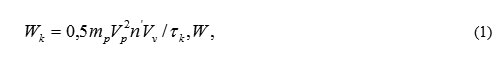
where m – mass of a PS particle, kg.
The mass of a PS particle is determined by the median diameter of dp:
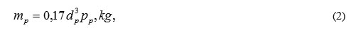
where p – density of material of PS particles, kg/m3; n’ – number of PS particles in volume unit which gets in contact with a foamy layer, 1/m3.
Value n’ is counted on a formula:
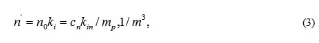
where n0 – total number of PS particles directed to active cleaning zone in its volume unit, 1/m3; cn — concentration of PS particles in entrance section of active cleaning zone, kg/m3; kin – coefficient of inertial capture of PS particles by a foamy layer.
Having conditionally accepted that the capture process of PS particles by a foamy layer is similar to subsidence of particles on a flat plate, coefficient of inertial capture of PS particles by a foamy layer can be determined with the formula:
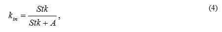
where A – dimensionless coefficient that gets considerable divergences in assessment by different authors explained with its dependence on the PS particles size and their movement speed.
Stokes’s criterion for a foam layer is determined by the formula:
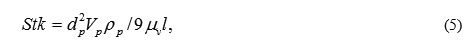
where μv – dynamic air viscosity, 1,82·10-5, Pa.
Speed of PS particles Vp in entrance section of cleaning active zone depends on the speed of the mainstream movement.
Having substituted dependences (2)-(5) to formula (1) and having executed the corresponding mathematical transformations, we receive:
At the second stage when PS particles approach foamy bubbles up to intermolecular forces action distance, the wedging pressure arising between particles and bubbles, connected with formation of the adsorptive air shells on particles and bubbles and featured with their interaction at phases section border obstructs their traffic. This first stage of cleaning process is characterized by the power WM parameter considering work of adhesion forces connected with superficial phenomena:
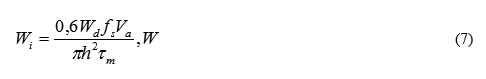
where Wd ~ 10-28 – the energy of dispersive interaction characterizing attraction force between PS particle and foamy bubble, J; fs – the surface area of intermolecular interaction of PS particle and bubble determined by the formula:
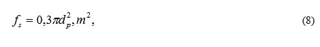
where Va – the foamy layer active zone, i.e. foamy layer volume with the greatest intensity of PS particles capture can be determined by the formula:
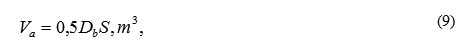
where Db – the average foamy bubble diameter, m is defined depending on foam properties (frequency rate, density and firmness) which in turn depend on a way of its receiving; τm – intermolecular interaction time between a PS particle and a foamy bubble determined by the formula:
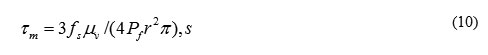
where Pf – pushing together PS particles and foam bubbles force which is defined, mainly, by kinetic energy of the particle spent for overcoming the distance of intermolecular forces:
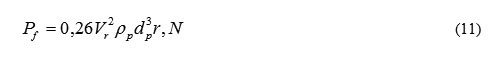
where r – intermolecular forces action distance, m.
Having substituted (8) – (11) in (7), we receive:
The second stage of air purification process with a foamy layer starts at the time of direct emergent contact between a PS particle and a foam bubble. The useful spent energy is foam counteraction of PS to stream. Here it is possible to determine two main, interconnected physical mechanisms (stages):
- elastic interaction of PS particles and foam bubbles;
- PS particles damping with a foamy layer.
Depending on received foam properties and taken PS particles each of mechanisms is revealed in various degree.
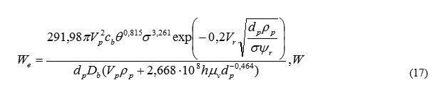
The parameter considering elastic energy and elastic interaction of foam and PS particles is possible to be presented as the sums of two power describing energy parameters We and Wp profitably spent at elastic and moistening interaction mechanisms.
The elastic mechanism of PS particle interaction with a foam bubble can be describes as follows: a particle adjoining a bubble stretches its surface in a contact place, forming deepening. As a result energy efficiency parameter can be determined depending on pressure inside the bubble and surface areas of particle and bubble interaction:

where σ – superficial tension of foam generator solution, J/m2; kn1 – coefficient of particles capture at the elastic mechanism of interaction.
It is known that the coefficient of PS particles capture with foam exponentially depends on the key parameters of these particles movement. For the elastic mechanism of interaction of a foamy layer with PS particles the equation is received:
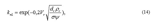
where Ψ — the coefficient of elastic interaction determined by the formula:
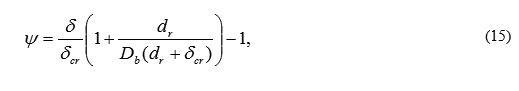
where βe — coefficient characterizing a share of elastic mechanism interaction with PS particles with foam at air purification with a foamy layer. The coefficient βe depends on a contact angle of Φ particles and a superficial solution tension and is determined by the formula:
![]()
Having substituted (14) – (16) to (13), we receive the expression:
Power parameter considering damping energy is determined by the formula:

where kn2 — coefficient of PS particles capture with foam at the moistening mechanism, as in the formula:
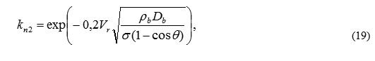
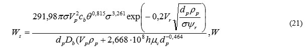
where ρb — foam density of , kg/m3; τs — time of spreading the solution on a particle surface.
τb is determined by the formula received as a result of experimental data processing:
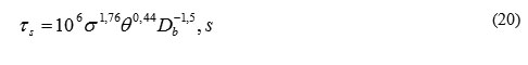
Then the Ws power parameter is determined by the formula:
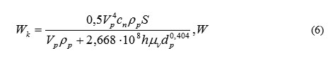
By experimental and theoretical studies it is established that electro loaded foam use allows to increase significantly the efficiency of air purification when electric forces act on all stages of cleaning process. The parameter considering electric forces power is determined by the formula:
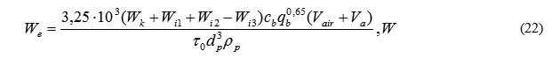
where –Wk, Wi1, Wi2, Wi3 are the parameters considering Coulomb force, induction power between the charge on foam and the induced charge on a particle, induction power between the charge on a particle and the induced charge on foam, interaction forces between particles consequently.
The parameters considering energy consumption of air stream for foam formation, moving it to foam generator under foaming agent solution pressure and foam electro recharge may be determined with the following formulas:
for air supply for foam formation taking into account the stream continuity equation:
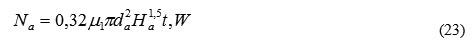
for foaming agent solution supply of foam generator:

where μ1, μ2– coefficients of expense of exhaust air and solution outlets; da, ds – diameters of bringing branch pipes of the irrigating device (nozzle) sections for air supply and foaming agent solution, m; rf– density of foaming agent, kg/m3; Ha, Hs – air and solution pressure, Pa; t – number of the mesh or bubbling foam generators necessary for the foamy layer creation on the whole cross section of the air purification active zone.
The power parameter Ne at artificial electro recharge of foam is equal to tension source power.
As a result of the conducted researches (Bespalov V.I et al., 2013) the dependence of the energy efficiency parameter of purification process with a foamy layer is received:
parametrical dependence of efficiency of the foamy method when receiving foam on a mesh or by bubbling:
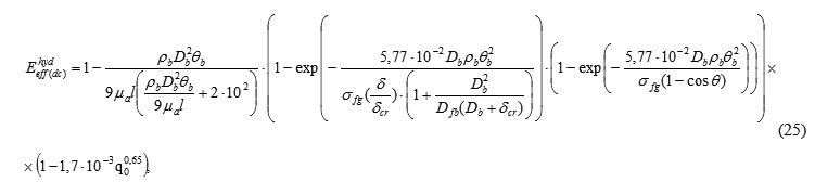
where l – length of cleaning active zone (zone of stable of foam bubbles existence), m; n2 – the coefficient characterizing actual and critical ratio of PS particles size for foamy bubbles; δ, δcr – consequently actual and critical average thickness of foam bubbles film, m; q0 – specific electric foam charge, C/kg;
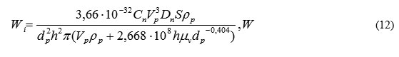
parametrical dependence of a energy efficiency parameter:
where Ff – the area of foaming section (foam supply), m2; i – number of the same type foam generators necessary for full overlapping of cleaning active zone cross section, piece; R – average distance between foam bubbles and PS particles in cleaning active zone, m; no – specific quantity of PS particles entering cleaning active zone, 1/m3; n΄ – specific quantity of the PS particles facing foam bubbles and getting into intermolecular interaction, 1/m3;
n΄΄ – specific quantity of PS particles on the surface of which damping process with foamy bubbles is realized, 1/m3;
n΄΄΄ – specific quantity of PS particles that stay on foam bubbles surface due to electric forces action, 1/m3.
The results of the calculations of ventilating air purification process (of flue gases) of toxic components and energy efficiency parameter data are presented in figure 3.
The physical essence of hydrodynamic method of ventilating air and flue gases purification from the polluting substances (toxic components) with application of foamy aerosol received by means of nozzle is in the purposeful impact on PS particle’s getting to active cleaning zone, which is in advance prepared according to “external” disperse system parameters presented by foamy aerosol bubbles possessing the moistening properties providing division of disperse phase (polluting substance particles) and ventilating air (main stream of flue gases) with the subsequent emission of cleared air (cleared gases) to atmosphere.
The technological scheme of realization of the hydrodynamic method of ventilating air and flue gases purification from the polluting substances (toxic components) with application of the foamy aerosol received by means of a nozzle is submitted in figure 4.
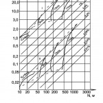 |
Figure 3: Existence area of energy efficiency parameter values of ventilating air (flue gases) purification process of toxic components with foamy layer |
The principle of action of the technological scheme goes as follows. Water from the main economic water supply system 1 via electromagnetic valve 2 comes to working liquid reservoir 4 in which is maintained automatically by means of ALR 3. From working liquid reservoir 4 water is pumped to the mixer 11. At the same time foaming agent from the storage 6 moves to the batcher 10, and then – to the mixer 11. The batcher 10 provides the demanded consumption of foaming agent, and the mixer 11 provides the set concentration of foaming agent solution. By means of pumping plant 12 ready foaming agent solution moves to sprinkler 9. External air also moves to sprinkler 9 via compressor plant 16, airintake 14 and air cleaner filter 15.
As a result the irrigating device (sprinkler) 9 in the active zone of cleaning process realization 7 forms the dispersed liquid spray cone consisting of foamy aerosol bubbles with distinct moistening properties which facing PS particles, moisten them and get precipitated from air stream, providing its cleaning of PS particles. Then the cleared air stream is directed to emission in the atmosphere. Thus, the formed sludge is directed to drainage. To provide the batcher 10, the mixer 11, pumping plant 12 and compressor plant 16 service ALR 5 is installed. To provide foaming agent solution pressure and compressed air control manometers 8 are installed at the irrigating device (nozzle) 9. In order to avoid foam missing from the cleaning active zone 7 the foam collector 13 is set.
Mathematical description of the hydrodynamic method of ventilating air and flue gases purification from the polluting substances (toxic components) with application of foamy aerosol received by means of nozzle performed by authors was also consolidated to obtain parametrical dependences of efficiency and energy efficiency parameter of the considered cleaning process. As a result of the researches conducted similar to foamy layer application by authors following dependences were received by the authors.
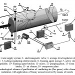 |
Figure 4: The technological scheme of purification of ventilating air (flue gases) with a foamy way process realization with application of foamy aerosol received by means of nozzle |
1- main economic water supply system; 2- electromagnetic valve; 3- average level regulator (ALR); 4- working liquid reservoir; 5- locking regulating reinforcement; 6- foaming agent storage; 7- active cleaning zone; 8- manometers; 9- sprinkler; 10- foaming agent batcher; 11- mixer; 12- pumping plant; 13- foam collector; 14- air intake; 15- air cleaner; 16- compressor plant
Parametrical dependence of efficiency of foamy cleaning process with foamy aerosol application may be calculated with the following formula:
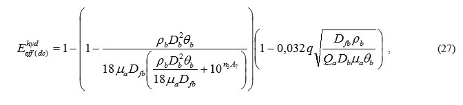
where Dfb – average foamy bubbles median diameter, m; n3 – coefficient characterizing a ratio of the actual and critical speed of PS particles and foam bubbles movement; A7 – coefficient of active cleaning zone overlapping completeness of cross section with foamy aerosol; ρb – foaming agent solution density, kg/m3; Qa – consumption of foaming agent solution at the sprinkler output section, m3/s.
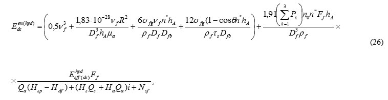
The parametrical dependence of the energy efficiency parameter of the foamy cleaning process with foamy aerosol application can be calculated with the formula:
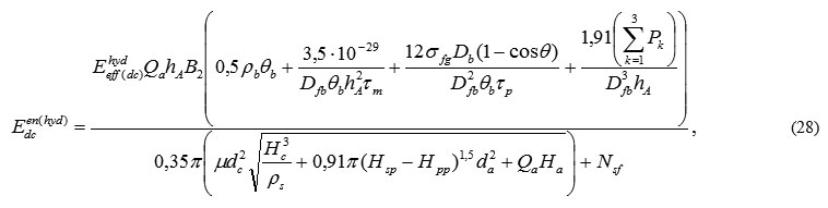
where τм– time of dynamic contact of a PS particle with a foam bubble, s; τр– time of wetting of a PS particle with a foam bubble, s; Рк– electric forces (Coulomb and induction) participating in interaction of a PS particle and a foam bubble, N; Нsp– total pressure in the section of the forcing (sucking in) branch pipe of the draft activator , Pa; Нpp– total pressure losses on the pipeline from the section of the forcing (sucking in) branch pipe of the draft activator to active cleaning zone, Pa; Qa– consumption of the compressed air given to sprinkler, m3/s; Ha– pressure of compressed air at sprinkler, Pa; Nsf– power of a source of artificial foam electrization, W.
The calculation results of Eef and Ee are presented in the form of schedules in figures 5-6.
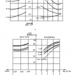 |
Figure 5: Dependence of efficiency and energy efficiency parameter of the process of ventilating air (flue gases) purification of toxic components with foamy aerosol (comovement of PS particles and foam bubbles) |
Нp – pressure of foaming agent solution; σ – superficial tension of foaming agent solution; Vair – speed of air stream movement in the active cleaning zone, m/s
I – comovement of PS particles and foam bubbles; II – oncoming traffic of PS particles and foam bubbles
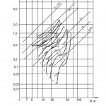 |
Figure 6: Existence area of energy efficiency parameter of process of ventilating air (flue gases) purification of toxic components with foamy aerosol |
Conslusion
As a result, the received parametrical dependences of efficiency and energy efficiency parameter make it possible to solve the problem of ecological efficiency assessment and energy efficiency of the technology of ventilating air and flue gases purification based on foam use. Thus, the analysis of graphic dependences (figure 3,5,6) allows us to make conclusions on the most effective way of foam supply for these or those production and technological conditions taking into account profitability of the applied method.
References
- Ann T.W. Yu, Yuzhe Wu, Bibo Zheng, Xiaoling Zhang, Liyin Shen (2014) Identifying risk factors of urban-rural conflict inurbanization: A case of China. Habitat International, Volume 44, 177-185.
- Bespalov VI, Gurova OS, Samarskaya NS, Lysova EP, Mishchenko AN (2014). Development of Physical and Energy Concept for Assessment and Selection of Technologies for Treatment of Emissions from Urban Environment Objects. BIOSCIENCES BIOTECHNOLOGY RESEARCH ASIA, December 2014. Vol. 11(3), 1615-1620.
- Bespalov V. I., Gurova O. S. (2012) The analysis of possible applications of air dust removal technologies at the enterprises of the construction industry. Scientific Review. No. 6. 193-195.
- Bespalov V. I. (2005) Processes and devices of environmental protection. / V. I. Bespalov, S. V. Meshcheryakov, O. S. Gurova (2005) Ministry of Science and Education of the Russian Federation, State Federal Educational Institution “Rostov State University of Civil Engineering”. Rostov-on-Don.
- Bespalov V. I., Gurova O. S., Samarskaya N.S., Paramonova O. N., Mishchenko A.N. (2013) Application of the disperse systems theory for the description of features of behavior of toxic components of the departing and exhaust gases of stationary and mobile sources of the urbanized territories. Engineering Bulletin of Don. V. 27. No. 4. Page 286.
- Kazuhiro Yuki Maricq M.M. (2013). Monitoring motor vehicle pm emissions: an evaluation of three portable low-cost aerosol instruments. Aerosol Science and Technology. V. 47. № 5, 564-573.
- Marc Antrop (2004) Landscape change and the urbanization process in Europe. Landscape and Urban Planning, Volume 67, Issues 1-4, 9-26.
- Paul Waley (2009) Distinctive patterns of industrial urbanization in modern Tokyo. Journal of Historical Geography, Volume 35, Issue 3, 405-427.
- Qingsong Wang, Xueliang Yuan, Jian Zhang, Ruimin Mu, Huichun Yang, Chunyuan Ma (2013) Key evaluation framework for the impacts of urbanization on air environment – A case study. Ecological Index, Volume 24, 266-272.
- Sukko Kim (2005) Industrialization and urbanization: Did the steam engine contribute to the growth of cities in the United States, Explorations in Economic History, Volume 42, Issue 4, 586-598.
- Vavilova T.Y. (2009) Background of regulation of planning and development of multifunctional industrial and residential areas. Privolzhsky Scientific Journal. № 4, 100-105.

This work is licensed under a Creative Commons Attribution 4.0 International License.


