

Manuscript accepted on : 05-Dec-2018
Published online on: 24-12-2018
Plagiarism Check: Yes
Controlled Wheelchair System Based on Gyroscope Sensor for Disabled Patients
Auns Q. H. Al-Neami and Saba M. Ahmed
Biomedical Engineering Department, College of Engineering, Al-Nahrain University, Baghdad, Iraq.
Corresponding Author E-mail: sabamohamed94@yahoo.com
DOI : http://dx.doi.org/10.13005/bbra/2703

ABSTRACT: The objective of this study is to provide the physically disabled patients who had suffered from losing their extremities due to the accident, age or disease, with an easily controllable wheelchair. Those patients cannot use the manual wheelchair or electric wheelchair with joysticks due to their handicap. The movements of this wheelchair are controlled by head motions with the use of gyroscope sensor. The microcontroller is also used and it is programmed to make the wheelchair moves according to the corresponding motion from the patient’s head. Forward movement of the wheelchair due to tilting head forward, left tilt of the user's head will cause the wheelchair to move to the left and so on. An obstacle detection system is done by using ultrasonic sensors. This system showed very good results it will make the usage of this wheelchair safer as compared to standard ones. It will help in enhancing the quality of life for such people and make them less dependent on others. This wheelchair is low cost, provide ease of use and comfortable for the physically disabled patients.
KEYWORDS: Gyroscope Sensor; Ultrasonic Sensor; Wheelchair System
Download this article as:| Copy the following to cite this article: Al-Neami A. Q. H, Ahmed S. M. Controlled Wheelchair System Based on Gyroscope Sensor for Disabled Patients. Biosci Biotech Res Asia 2018;15(4). |
| Copy the following to cite this URL: Al-Neami A. Q. H, Ahmed S. M. Controlled Wheelchair System Based on Gyroscope Sensor for Disabled Patients. Biosci Biotech Res Asia 2018;15(4). Available from: https://www.biotech-asia.org/?p=32198 |
Introduction
The quality of life for physically disabled patients and handicappers should be enhanced by using practical, sophisticated and cost-effective locomotive devices. The need for human intervention had minimized because today’s technology has shifted to automation. These automated systems have less manual operations with high accuracy and reliability. Smart wheelchairs are very much helpful for disabled patients who have difficulties in driving manual wheelchairs. Patients who had losing their hands cannot use the manual wheelchair or motorized wheelchair with joysticks. Medical devices produced to help such patients are very complicated and expensive. So, a microcontroller based system that enables the movements of the wheelchair depending on the head motion is introduced. The system describes a wheelchair for physically disabled patients which use head motion and gyroscope sensor interfaced with DC motor. Gyroscope sensor is a micro-electro-mechanical sensor (MEMS) sensor which effectively translated the head movements into computer interpreted signals. The obstacle detection system with the use of ultrasonic sensors will help the patient to drive the wheelchair safely.
There are many studies related to the present study:
In (2014), Vishal,1 implemented the control of the wheelchair by hand gesture recognition. This development wheelchair is helpful for the physically disabled people and it can be used in hospitals or during their daily life. They can control the directions of the wheelchair depending on the movements of his hand (hand gestures). This is done with the use of accelerometer sensor which in turn controls the wheelchair with the help of hand gesture. It provided a controllable wheelchair that has the ability to move freely in all directions.
In (2015), Sachin,2 designed and developed a system that allowed the user to interact with the wheelchair at different levels of the control and sensing. A segment of the disabled community finds it difficult or impossible to use wheelchairs either powered or manual wheelchairs due to their disability. This study describes a wheelchair for physically disabled people in which a dependent-user recognition using hand movements to get movements of a wheelchair in four directions, forward, backward, left and right. For this purpose accelerometer sensor was used, and an IR sensor was installed on the chair as obstacle sensors for detection of wall obstacle in the backward direction. The final results produced a type of powered wheelchairs that give off the needs of many individuals with disabilities.
In (2016), Harshal,3 designed and developed a smart automated wheelchair. It is useful for elder and handicapped patients. They can transport easily without depending on others. This smart wheelchair is mainly divided into three systems: voice recognition system, gesture control system and an obstacle detection system. In this study, the wheelchair can be controlled by voice commands with the help of a gesture recognition system. The gesture recognition system depends on the accelerometer sensor which is a low cost and could provide the direction of the hand so it helps to recognize the gestures. This study provided an easily controllable wheelchair for elder and disabled people they can drive it by themselves and with fewer efforts.
General Description
Electric Wheelchair
It is a chair with wheels that powered with DC motors to enable the patients to use it automatically. It is much easier than the manual wheelchairs. The DC motors can be charged using rechargeable batteries.
Gyroscope Sensor
Gyroscope means the rate of rotation around x, y and z-axes. The gyroscope sensor also is known as angular velocity (angular rate) sensor is a device that senses the angular velocity. The angular velocity is the change in rotational angle per unit of time. It is expressed in deg/s (degrees per second), as shown in fig (1).
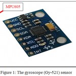 |
Figure 1: The gyroscope (Gy-521) sensor.
|
The gyroscope sensor (Gy-521) has four connections (VCC, GND, SDA and SCL) where VCC pin connected to 5V on microcontroller, GND to GND, SDA which is the data line connected to A4 on microcontroller and SDL which is the clock line connected to A5 on microcontroller, shown in fig.(2). The 6-axis motion tracking device is the microprocessor unit (MPU 6050) of this gyroscope sensor (Gy-521). It combines a 3-axis accelerometer sensor, 3-axis gyroscope sensor, temperature sensor, and a digital motion processor (DMP). All these are in a small package with a size of 4x4x0.9mm. For data transmission with the micro-controller, it uses a standard I2C bus via SDA & SCL. It receives inputs from an external 3-axis compass (which is a magnetometer that measures the strength and direction of the magnetic fields) to produce a complete 9-axis motion output due to its I2C bus.
The main parts of the MPU of Gy-521 sensor are:
Gyroscope sensor.
Accelerometer sensor.
Temperature sensor.
Digital motion processor.4
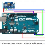 |
Figure 2: The connections between the sensor and the microcontroller.
|
Motor Drivers
The IBT-2 driver is using two high current half bridge Infineon BTS 7960 chip for motor drive applications. When a microcontroller is interfaced with this driver, it is made easy to use this driver which features are current sensing, rate protection and adjustment against overvoltage, under-voltage, over-current, short circuit, and over-temperature.
Although it has a small size, it is used to provide a cost-optimized solution for protected high current PWM motor drives.
Features:
The operating voltage between 5v to 27v.
Motor speed can be controlled by PWM up to 25 kHz.
Motor backward and forward motion control.
Power dissipation is reduced by switched mode current limitation.
Current limitation level of 30A current sense capability.
Over-voltage will lock out while over-temperature shutdown.
Heat sink with large size is mounted to the driver.
The size of the motor driver: 4x5x2cm.
The weight of motor driver: 66gm.
Connections with the microcontroller:
It is supplied by 5v from Arduino and GND is connected to Arduino GND.
Right drive_enable (R_EN) and left drive_enable (L_EN) shorted and connected to 5V level (high) which means enable of the motor driver to work, if they are connected to low (GND) this means close the work of the motor driver.
Left pulse width modulation (L_PWM) is high motor forward or the input PWM signal, right pulse width modulation (R_PWM) high motor reveres or input PWM signal both are connected to the digital pins in the microcontroller.5 The motor driver illustrated in fig (3).
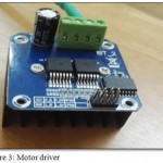 |
Figure 3: Motor driver
|
Microcontroller
The microcontroller is a small computer on a single integrated circuit. It is consisting of a processor core, programmable input and output peripherals and also memory. It is open-source. Open-source means that anyone of thinkers or hobbyists can make his own electronic project with his/her own program or design which can be modified and developed for future work. There are many types of microcontrollers. Mega 2560 is one of them; it is employed and programmed to control the whole implemented electrical circuits.6
Power Supply
The power for the DC motors of the wheelchair is supplied by a battery. There are two types of batteries rechargeable and non-rechargeable battery. The rechargeable one is also called a storage battery, accumulator or secondary cell. This type of electrical batteries can be charged, discharged occurred during load and recharged again several times. The primary or non-rechargeable battery is supplied fully charged and then castaway once discharged.
The rechargeable battery is composed of one or more electrochemical cells. The idiom ‘accumulator’ is used for the expression of the accumulation and storage of energy through a reversible electrochemical reaction. There are several shapes and sizes of batteries. They are ranging from button cells to megawatt system. They are used to stabilize an electrical distribution network by connecting them together. Rechargeable batteries as compared with the disposable ones are initially costly batteries, but they have a much lower total cost of ownership and environmental effect, as they can be recharged inexpensively more than one time before they need to be replaced. There are some types of rechargeable batteries come in the same sizes and voltages as disposable types; they can be used interchangeably with them.
This section of rechargeable batteries deals with the requirements of power applied to the wheelchair content such as DC motors, microcontroller, ultrasonic sensor, and other parts.7
Experimental Work
A smart wheelchair with its motion controlled by head gestures is the goal of the present study, as already explained. For this study, first, the motor drivers are connected to the wheelchair in order to control the movement of its wheels. For each DC motor one motor driver is employed. The VCC, GND are feeding by mega 2560 microcontroller, also the digital pins of motor drivers are all connected into digital pins of the microcontroller. The direct connection between motor drivers and the power supply of the system also take place. Two batteries of 12v are applied in a serial connection manner in order to supply 24v for the motors of the wheelchair. Fig (4) shows these connections.
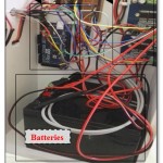 |
Figure 4: Connections of motor drivers, microcontroller, and batteries.
|
The main part of the work is to connect the gyroscope sensor (motion control sensor). After that the connections of the gyroscope sensor with the microcontroller built up, as mentioned in section 2.2, two steps take place:
Locate the reference point for the sensor.
Estimate the four directions according to the taking reference point.
Locating the reference point is done by holding the sensor stable for 3 sec. then according to try and error four mathematical equations are put to control the four directions of the wheelchair.
These models are
X1 = xref – 5000
For the front movement, the mathematical model as:
X2 = xref + 5000
Where:
X2: is the instantaneous reading of the sensor that responsible for satisfying the back condition.
Xref: represents the reference point calculated by the sensor when it holds stable at the beginning of operation into x-axis direction.
For the right movement, the mathematical model as:
Yl = yref – 3000
Where:
Y1: is the instantaneous reading of the sensor that responsible for satisfying the right condition movement.
Yref: represents the reference point calculated by the sensor when it holds stable at the beginning of operation into y-axis direction.
For the left movement, the mathematical model as:
Y2 = yref + 4000
Where:
Y2: is the instantaneous reading of the sensor that responsible for satisfying the left condition movement.
Yref: represents the reference point calculated by the sensor when it holds stable at the beginning of operation into y-axis direction.
For sensor placements, a special headpiece is designed to place the sensor on it so; it will sense the patient’s head gesture easily. In which each gesture will cause movement of the wheelchair to the same side.
It is sewed with a diameter of 20cm and height of 12 cm. An elastic fabric is used for this purpose so it can fit many sizes of the user’s heads. It must be placed on the head, as shown in fig (5) with the gyroscope wire connection directed to the back of the head because all the conditions of the directions are applied on this position. The connections of the gyroscope sensor with the microcontroller are:
VCC connected to 5V.
GND connected to GND.
SDA connected to the digital pin A4 in the microcontroller.
SCL connected to the digital pin A5 in the microcontroller.
All these connections are shown in fig (6).
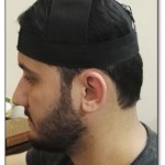 |
Figure 5: Headpiece placement.
|
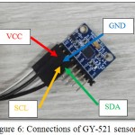 |
Figure 6: Connections of GY-521 sensor.
|
The placement of the Gy-521 sensor is shown in figure (7). It is centered on the top of the head so the first reading of the sensor will calculate at this location which represents the stop position of the wheelchair. These reading represent Xref and Yref for the mathematical models. The conditions for each wheelchair’s direction will be compared with them.
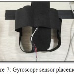 |
Figure 7: Gyroscope sensor placement.
|
Then the protection system is connected for the wheelchair by using (ultrasonic sensors) in the back of the chair and in front of it in order to find out if there are any obstacles in the patients’ way. If so the wheelchair will stop to notify the user to change his way. The maximum distance that can be sensed by the ultrasonic sensor between the wheelchair and the obstacle is 75cm. It is a good distance for the user to change his way. Fig (8), illustrates the ultrasonic sensor location.
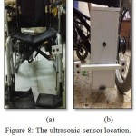 |
Figure 8: The ultrasonic sensor location.(a): front view (b): back view.
|
Results
In the present study which includes a design for the wheelchair that can be smoothly controlled in different directions with the user’s head gesture. Each head gesture is responsible to perform a wheelchair movement. The whole system is protected through the use of ultrasonic sensors. These sensors would stop the wheelchair from movement if there is an obstacle in the wheelchair’s path.
Wheelchair Movements
Stop Position
The stop position is the reference position of the wheelchair. It is calculated at the first 3 sec from system operation. This first sensor’s reading is essential in controlling the other movements of the wheelchair. Fig (9) shows the position of the patient and the signal gained for the stop (reference) position.
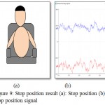 |
Figure 9: Stop position result (a): Stop position (b): Stop position signal.
|
Front Position
The front position is depending on the mathematical model mentioned in section 3. In which X1 is calculated after the condition was satisfied to produce the forward movement. This movement will depend on pointing the user’s head into the forward direction. Fig (10) shows the position of the patient and the signal gained for the front position.
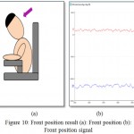 |
Figure 10: Front position result (a): Front position (b): Front position signal.
|
Back Position
The back position is depending on the mathematical model mentioned in section 3. In which X2 is calculated after the condition was satisfied to produce the backward movement. This movement will depend on pointing the user’s head into backward direction. Fig (11) shows the position of the patient and the signal gained for the back position.
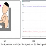 |
Figure 11: Back position result (a): Back position (b): Back position signal
|
Right Position
The right position is depending on the mathematical model mentioned in section 3. In which Y1 is calculated after the condition was satisfied to produce the right movement. This movement will depend on pointing the user’s head in the right direction. Fig (12) shows the position of the patient and the signal gained for the right position.
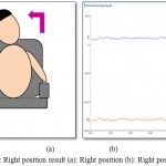 |
Figure 12: Right position result (a): Right position (b): Right position signal
|
Left Position
The left position is depending on the mathematical model mentioned in section 3. In which Y2 is calculated after the condition was satisfied to produce the left movement. This movement will depend on pointing the user’s head into left direction. Fig (13) shows the position of the patient and the signal gained from the left position.
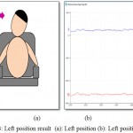 |
Figure 13: Left position result (a): Left position (b): Left position signal.
|
Discussion
This study gives an idea of how to control the wheelchair with the user’s head gestures only in various directions. The final results of this study were very interesting. For each head gesture, one of the wheelchair’s movement was satisfied –according to the applied conditions- to give of the required movement. For the obstacle detection system, the whole movement stopped when there is an obstacle. The system showed good results for the embedded circuit design.
Conclusion
This study proposed a work of a novel smart wheelchair with an obstacle detection system for driving safety. The hardware of the smart wheelchair is based on the gyroscope sensor interfacing with a microcontroller. This system employed the gyroscope Gy-521 sensor as the main component of the design to control the movements of the wheelchair according to the user’s head gestures. Ultrasonic sensors are the obstacle detection system that stops the wheelchair as it reaches to an obstacle. Interfacing all these sensors to the wheelchair was controlled by the microcontroller mega-2560. The developed system provides a safer environment for the elderly and the disabled; they can travel indoors or even outdoors alone with safety than before.
References
- Pande V. V., Ubale N. S., Masurkar D. P., Ingole N. R., Mane P. P. Hand gesture based wheelchair movement control for disabled person using MEMS. International Journal of Engineering Research and Applications. 2014;4(4):152-8.
- Patil S. S., Patil K. N., Patil S. P. International Journal of Engineering Sciences & Research Technology “Gesture Based Wheel Chairs for Physically Disabeld Persons”.
- Devade H., Kadam P., Karanjkar P., Pisal R. Review on Smart wheel chair for physically handicapped people. Imperial Journal of Interdisciplinary Research. 2016;2(3):305-8.
- Synacorp Trading and Services Provider, ” MPU60 50 GY-521 3 Axis Gyro Accelerometer Sensor Module Arduino “, data sheet, website(http://www.synacrop.my). 2014.
- Future electronics Provider, “High Current 30a Dc Motor Driver”, data sheet, website (http://www.fut-electronics.com).
- Synacorp Trading and Services Provider,” Arduino Mega 2560 Rev3 (Compatible)”, data sheet, website, (http://www.synacrop.my). 2014.
- Vision Rechargeable Products Provider, “High power Battery”, website (http://www.vision-batt.com ). 2014.

This work is licensed under a Creative Commons Attribution 4.0 International License.


